
Single-Boss Pivot Lever Arm: Design for Forging
A flat aluminum lever-arm blank had to be reshaped for closed-die forging, with complete filling of the die as the goal: the final design meets all nine published forging design rules. I set the parting line, draft angles (3° outside, 5° inside), fillets and web proportions, then checked each rule against published guidelines.
- Project
- Personal case study
- My role
- Design review, CAD, drawings and verification
- Tools
- SolidWorks
- Process
- Closed-die (impression-die) forging, EN AW‑6061 T6
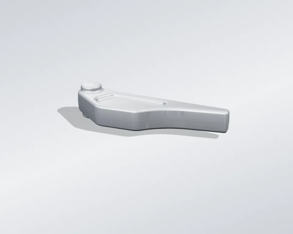
- 3° / 5°draft angle, external / internal
- 9/9design rules verified compliant against published forging guidelines
- R3–R100mmfillet & corner radius family
- Ø23.36mmpivot bore, finish-machined
Skills shown
How I did it
Take a flat CAD blank through a systematic design-for-forging review and confirm the resulting geometry is compliant with published forging design guidelines before it goes anywhere near a die designer.
-
Start from the blank
SolidWorks
A single-pivot lever-type forging: a slender, tapering arm connecting a circular pivot boss at one end to a flattened, radiused blade tip at the other. Typical of hand- or foot-operated levers, bell-crank control arms, and rocker or actuation linkages, where the part carries a bending and torsional load between the pivot and the tip while keeping mass low.
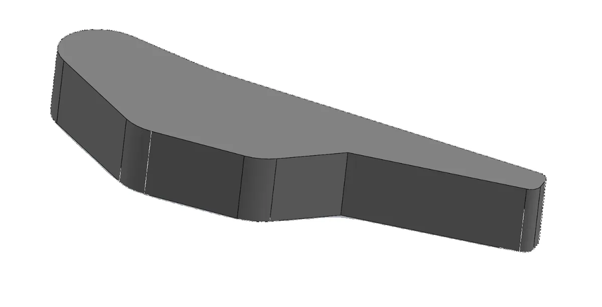
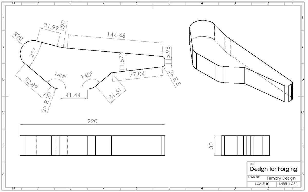
The Primary Design is the un-drafted, un-filleted starting envelope: a solid, uniform flat slab with sharp edges throughout.
- Blank envelope, L × W
- 220 × 30 mm
- Pivot bore
- Ø23.36 mm, finish-machined
- Draft, external / internal
- 3° / 5°
- Fillet & corner radii
- R3–R100 mm
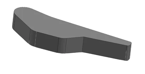
Primary Design surface blank, the un-drafted, un-filleted starting envelope. 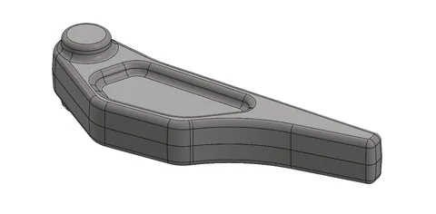
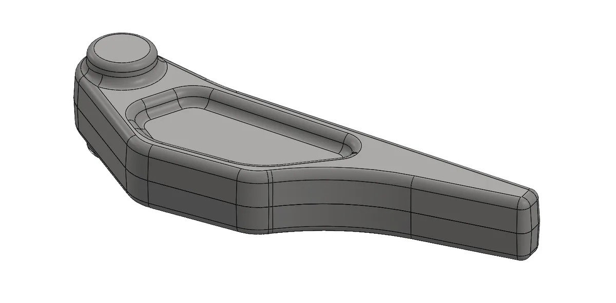
Final Design isometric CAD view (SolidWorks). -
Choose the material
Material selection
I adopted EN AW-6061 T6 as the reference forging alloy for its forgeability and good corrosion resistance, and benchmarked it against two higher-strength alternatives, EN AW-2014 T6 and EN AW-7075 T73.
The process route is closed-die (impression-die) forging.
- Alloy
- EN AW-6061 T6
- Forging temperature
- ≈ 450–500°C
- Forgeability
- Excellent
- Process
- Closed-die forging
Forging alloys compared Alloy Yield strength Forgeability EN AW-6061 T6 (adopted) ≈ 255–275 MPa Excellent EN AW-2014 T6 ≈ 415–440 MPa Good EN AW-7075 T73 ≈ 400–435 MPa Fair -
Apply the forging rules
SolidWorks
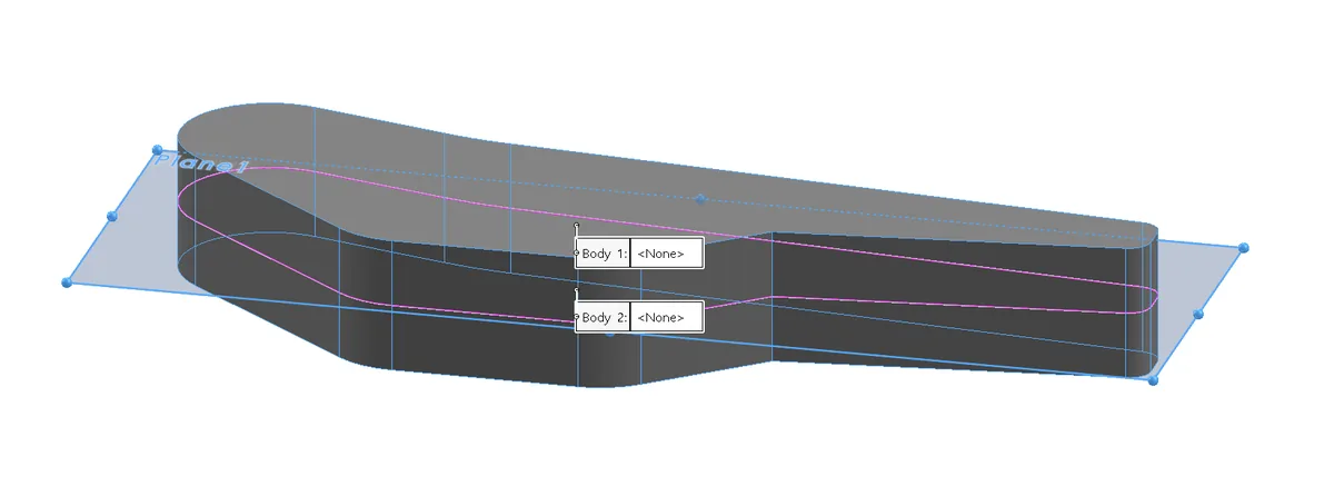
I selected the parting line along the plane of maximum projected periphery, splitting the part into two die halves with no re-entrant undercuts, and applied draft to every face parallel to the die-closing direction: 3° external, 5° internal, at the lower end of the aluminum guideline range.
I added a filleted weight-relief pocket and rib to the arm’s broad face, and a raised boss at the pivot end, increasing bending stiffness per unit mass. Every sharp edge was replaced with a fillet or corner radius sized well above the 2–3× fillet-to-corner guideline, keeping metal flow smooth and avoiding stress concentrations.
- Parting line
- Plane of maximum projected periphery
- Draft
- 3° external, 5° internal
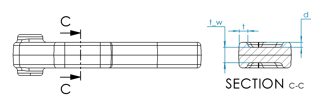
- Web, t / d
- 10 mm / 6 mm
- Inter-web thickness
- 18 mm (min. 6 mm)
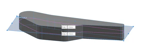
Parting-plane selection in SolidWorks, splitting the forging into upper and lower die-cavity halves. 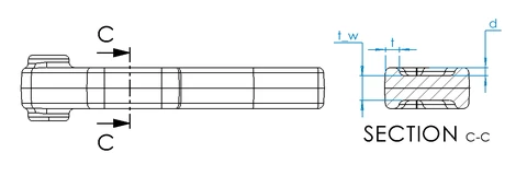
Web/rib section nomenclature (Section C-C): side thickness t, inter-web thickness tw, and web depth d. -
Compare before and after
SolidWorks drawings
I produced drawings of the Primary Design and the Final Design. Every feature in the flat Primary Design blank was reworked for forging on the way to the Final Design.
- Drafts
- None → 3° / 5°
- Corners / edges
- Sharp → R3–R100 mm
- Body section
- Solid slab → ribbed / webbed channel
- Pivot end
- Plain boss → raised boss, machined bore
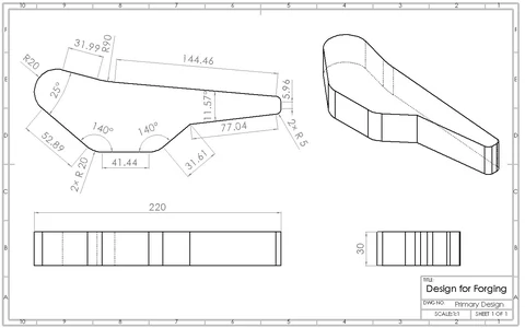
Primary Design drawing, blank envelope, pre-DFF. Select to enlarge. 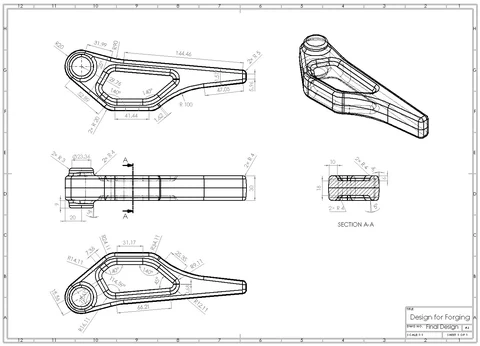
Final Design drawing, forging-ready geometry. Select to enlarge.
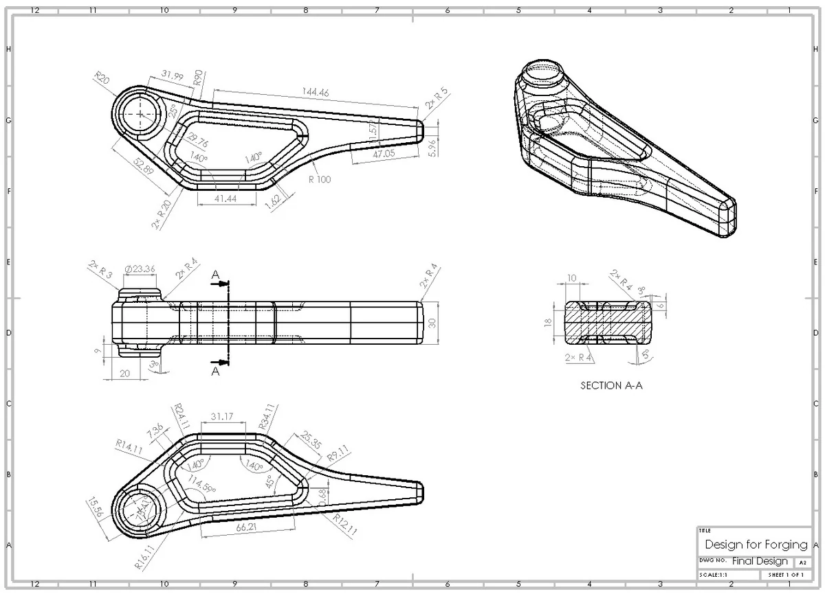
How I checked the design
The Final Design geometry checks out against published forging design guidelines (EN 10243, EN 586‑3, standard DFMA practice) on every rule applied, with several margins conservative rather than sitting at the guideline floor.
9/9
design rules verified compliant against published forging guidelines
Each rule applied in the method is checked here against a typical guideline range and the value actually achieved in the Final Design, covering parting-line location, draft angle, fillet ratios, web proportions, and the pivot bore.
| Design rule | Value applied | Guideline (Al. closed-die) | Status |
|---|---|---|---|
| Parting-line location | Upper / lower die-half split | Single flat plane, max periphery, no undercuts | Compliant |
| External (male) draft angle | 3° | 3°–5° | Compliant, lower bound |
| Internal (female) draft angle | 5° | 5°–7° | Compliant, lower bound |
| Fillet : corner radius ratio | ≈ 3–7× in most locations | R ≈ 2–3 × r | Compliant, conservative |
| Minimum corner radius | R3 / R4 / R5 mm applied | ≥ 3 mm typical, section depth ≈ 30 mm | Compliant |
| Web thickness-to-depth ratio | t = 10 mm, d = 6 mm | ≥ 1 : 6 | Compliant |
| Minimum inter-web thickness | 18 mm adopted | ≥ 6 mm minimum | Compliant, conservative |
| Pivot bore / hole in boss | Ø23.36 mm finish-machined | Forge solid, machine after forging | Compliant |
| Re-entrant (undercut) features | None present | None permitted without side-action tooling | Compliant |
Defects avoided by design
Each rule applied in the method directly mitigates one or more well-documented forging defect modes.
- Generous fillets and a bounded web ratio keep the metal-flow path smooth, so flow fronts fuse instead of folding over each other and forming cold shuts or laps.
- The d/6 ≤ t web rule and generous fillet radii keep material from cooling and losing plasticity before the die is fully filled, avoiding underfill.
- The same d/6 ≤ t ratio keeps a thin, deep web from buckling or folding under the die-closing load.
- Smooth fillet transitions keep the forging’s grain flow continuous and aligned with the load path, avoiding the flow-line disruption that would erode its fatigue-strength advantage.
- Generous internal radii avoid the sharp, thin die protrusions that crack under repeated thermal cycling, extending die life instead of accelerating heat-checking and wear.
Engineering judgment and recommendations
Beyond the compliance result, the review surfaces where the design has margin and where follow-on engineering work is still needed.
-
Flagged
Draft angles sit at the guideline floor
Both the external (3°) and internal (5°) draft angles are at the lower bound of the typical range for aluminum press forging. Achievable with a well-maintained die surface and a good release lubricant, but worth reviewing with the forging supplier once real tooling and lubrication data are available.
-
Metal-flow simulation would confirm die fill
The web-proportioning and fillet rules applied here are qualitative design-guideline checks. A die-fill / metal-flow simulation would numerically confirm complete die fill and quantify the defect risks flagged above.
-
Forging load and press tonnage not yet sized
This review covers geometry only. Forging-load estimation and press-tonnage sizing are needed before die design can proceed.
-
Confirm alloy against real service loads
EN AW-6061 T6 is the reference alloy here for its forgeability and cost. EN AW-2014 T6 or EN AW-7075 T73 remain drop-in options if a structural/fatigue load review calls for extra strength margin.
Technical details
Full material and design-change data for engineers who want to go deeper.
Material selection Density, strength, elongation, forging range and forgeability of the three alloys
Material selection
EN AW-6061 T6 is adopted as the reference forging alloy for its forgeability and good corrosion resistance, benchmarked here against two higher-strength alternatives.
| Property | EN AW-6061 T6 | EN AW-2014 T6 | EN AW-7075 T73 |
|---|---|---|---|
| Density | 2.70 g/cm³ | 2.80 g/cm³ | 2.81 g/cm³ |
| Ultimate tensile strength | ≈ 290–310 MPa | ≈ 455–480 MPa | ≈ 470–505 MPa |
| Tensile yield strength | ≈ 255–275 MPa | ≈ 415–440 MPa | ≈ 400–435 MPa |
| Elongation at break | ≈ 10–17% | ≈ 7–13% | ≈ 8–13% |
| Typical hot-forging range | ≈ 450–500°C | ≈ 420–460°C | ≈ 380–440°C |
| Relative forgeability | Excellent | Good | Fair |
Method and design evolution The four design operations, and how every feature changed from blank to Final Design
Method
Four design operations, applied in sequence, convert the flat blank into forging-ready geometry: parting-line selection, draft angle, rib/web/boss addition, and fillet application.
Web design rule: d / 6 ≤ t (side thickness vs. web depth) | tw ≥ 6 mm minimum inter-web thickness
- Parting line selected along the plane of maximum projected periphery, splitting the part into two die halves with no re-entrant undercuts.
- Draft angle applied to every face parallel to the die-closing direction: 3° external, 5° internal, at the lower end of the aluminum guideline range.
- A filleted weight-relief pocket and rib added to the arm’s broad face, and a raised boss at the pivot end, increasing bending stiffness per unit mass.
- Every sharp edge replaced with a fillet or corner radius sized well above the 2–3× fillet-to-corner guideline, keeping metal flow smooth and avoiding stress concentrations.
- Web depth is bounded to six times the web side thickness (d ≤ 6t), with inter-web thickness held at 18 mm against a 6 mm minimum, to prevent buckling and underfill.
Design evolution
Every feature in the flat Primary Design blank was reworked for forging on the way to the Final Design, summarized feature by feature below.
| Feature | Primary Design | Final Design |
|---|---|---|
| Drafts | None, vertical, un-drafted faces | 3° external / 5° internal, on faces parallel to the die-closing direction |
| Corners / edges | Sharp edges throughout | Fully filleted, R3–R100 mm family |
| Pivot end | Plain rounded boss, no bore | Raised boss, 2× R3 mm flange fillets, machined Ø23.36 mm bore |
| Body cross-section | Solid, uniform flat slab | Ribbed / webbed open-channel section with weight-relief pocket |
| Tip | Flat tapered blade, 2× R5 mm fillet | Same envelope, refined to 2× R4 mm (section) / 2× R5 mm (profile) |
| Parting line | Established, upper / lower die-half split | Retained as the draft-direction reference |
| Manufacturing readiness | Concept / envelope model only | Forging-ready: compliant with draft, fillet, and web/rib rules |