
Ribbed Boss-and-Socket Fitting: Design for Injection Molding
A solid-block plastic fitting had to become a part that molds cleanly in a simple two-plate injection mold: the redesigned ABS part has uniform 2.0 mm walls, weighs 20.12 g and meets all nine published molding rules. I applied parting-line, wall, draft, rib and fillet rules; the thicker mounting flange is the one spot to inspect on the first parts.
- Project
- Personal case study
- My role
- Design review, CAD, drawings and checks
- Tools
- SolidWorks
- Process
- Injection molding (2-plate, cold-runner), ABS
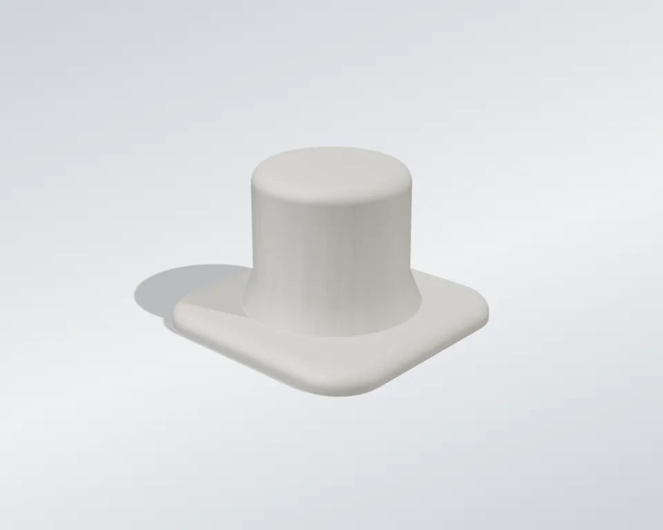
- 2.0mmshell nominal wall thickness
- 0.5°draft angle, all mold-pull faces
- 9/9design rules verified compliant against published injection-molding guidelines
- 20.12gpart mass in ABS, recorded on the Final Design drawing
Skills shown
How I did it
Take a solid CAD blank through a systematic design-for-injection-molding review and confirm the resulting geometry is compliant with published DFM-IM guidelines before it goes anywhere near a mold builder.
-
Start from the blank
SolidWorks
A small, hollow, open-top cylindrical socket rising from a solid, corner-radiused square mounting flange, reinforced by four internal cross ribs. Typical of caster and leg-mounting sockets, tube- or post-support bosses, and bushing or bearing housings on a molded plastic frame or panel.
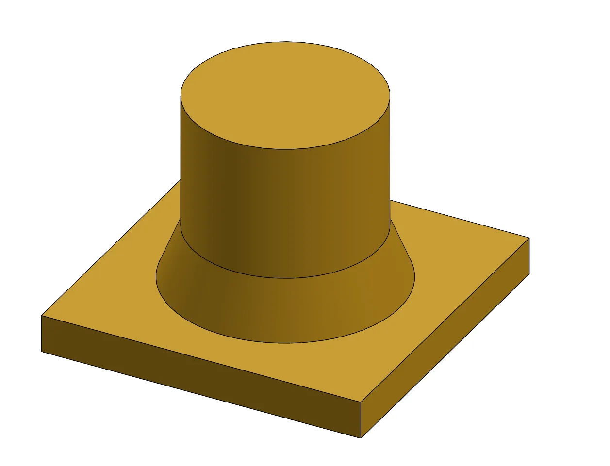
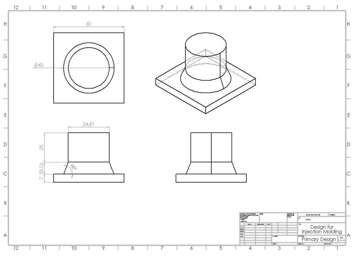
The Primary Design is a solid, un-shelled, un-filleted, un-drafted CAD blank fixing the part’s overall envelope.
- Mounting flange
- 64 × 64 mm, R10 corner
- Boss / socket OD
- Ø39.25 mm
- Shell wall
- 2.0 mm nominal
- Draft
- 0.5°, all mold-pull faces
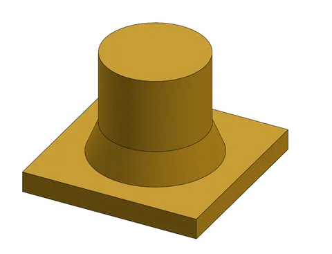
Primary Design surface model (SolidWorks): a solid, un-shelled, un-filleted, un-drafted CAD blank fixing the part’s overall envelope. 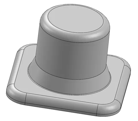
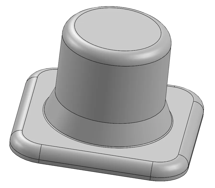
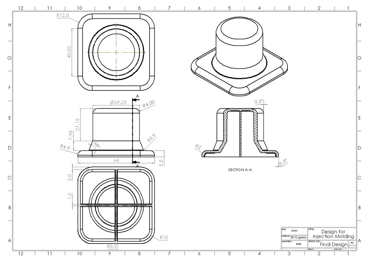
Final Design isometric CAD view (SolidWorks): shelled boss/socket, flange corner fillets, and drafted mold-pull faces. -
Choose the material
Material selection
The Final Design drawing specifies ABS as the molding material and records a part mass of 20.12 g. Its forgiving process window and dimensional predictability at the shelled boss’s thin wall confirm it as an appropriate choice. I benchmarked it against two higher-performance alternatives, POM (acetal homopolymer) and 30% glass-filled PA66.
- Material
- ABS
- Part mass
- 20.12 g
- Mold shrinkage
- ≈ 0.4–0.7%
- Process
- Injection molding, 2-plate, cold-runner
Materials compared Material Tensile strength Mold shrinkage ABS (specified) ≈ 38–45 MPa ≈ 0.4–0.7% POM (acetal homopolymer) ≈ 62–70 MPa ≈ 1.8–2.5% PA66, 30% glass-filled ≈ 150–180 MPa (dry) ≈ 0.3–0.6% (anisotropic) -
Apply the molding rules
SolidWorks
I placed the parting line at the flange underside, splitting the mold into a core and cavity that separate along a single flat plane, with no undercut or re-entrant feature anywhere in the model. I shelled the boss/socket from a solid section down to a uniform 2.0 mm wall, thin enough to cool evenly and hold the sink, void, and warp risk down, and applied a 0.5° draft to every mold-pull-direction face.
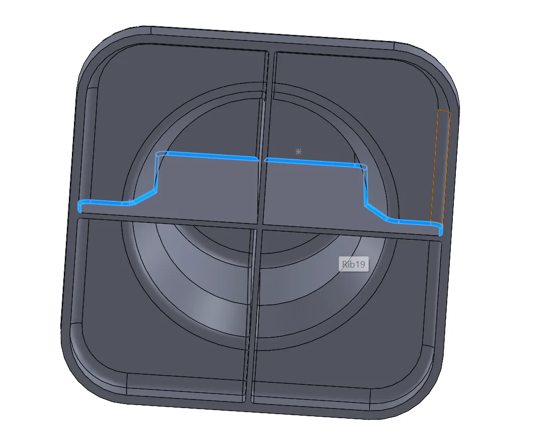
Four ribs at 90° intervals, each 1.2 mm thick (0.6× wall), stiffen the shelled wall against bending without the sink-mark risk of a thicker section. Every sharp edge and internal corner is replaced with a fillet, with the boss’s internal/external radius pair (R2 / R4.00) sized to hold the wall’s constant thickness through the bend.
- Parting line
- Flange underside
- Shell wall
- 2.0 mm
- Draft
- 0.5°
- Ribs
- 4 × 1.2 mm at 90°
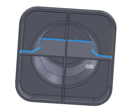
Rib-layout definition (SolidWorks feature view): four ribs are positioned at 90° intervals along the inner wall of the shelled boss. The blue line indicates the internal fillet at the rib–shell connections. -
Compare before and after
SolidWorks drawings
I produced drawings of the Primary Design and the Final Design. Every feature in the solid Primary Design blank was reworked for injection molding on the way to the Final Design.
- Boss / socket wall
- Solid → 2.0 mm shell
- Internal ribs
- None → 4 × 1.2 mm
- Draft
- None → 0.5° per side
- Corners / edges
- Sharp → R0.5–R12.0
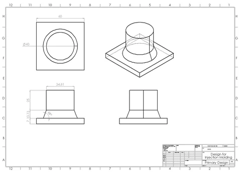
Primary Design drawing, blank envelope, pre-DFM-IM. Select to enlarge. 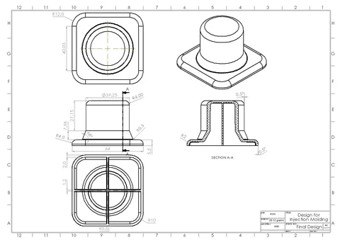
Final Design drawing, molding-ready geometry. Select to enlarge.
How I checked the design
The Final Design geometry checks out fully compliant against published injection-molding design guidelines (Malloy; Boothroyd, Dewhurst & Knight; DIN 16742) on all nine rules applied, with the mounting flange’s thickness ratio compliant but near the upper bound of the recommended range.
9/9
design rules verified compliant against published injection-molding guidelines
Each rule applied in the method is checked here against a typical guideline range and the value actually achieved in the Final Design, covering parting-line location, draft angle, wall and rib thickness, fillet ratios, and core proportions.
| Design rule | Value applied | Guideline (thermoplastic IM) | Status |
|---|---|---|---|
| Parting-line location | Flat plane at flange underside | Single flat plane, no undercuts | Compliant |
| Draft angle, all pull faces | 0.5° | ≥ 0.5° min (polished); 1–2° typical | Compliant, lower bound |
| Nominal shell wall thickness | 2.0 mm | ≈ 1–4 mm typical | Compliant |
| Rib-to-wall thickness ratio | 0.6 × wall (1.2 / 2.0 mm) | 0.5–0.75 × wall | Compliant |
| Internal fillet / wall thickness ratio | R2 / 2.0 mm = 1.0× wall | ≥ 0.5× wall min, 0.75× preferred | Compliant, conservative |
| External = internal + wall (constant-wall rule) | R4.00 = R2 + 2.0 mm, exact | Outer = inner + wall | Compliant |
| Flange-to-shell local thickness ratio | 5.5 / 2.0 = 2.75 : 1 | ≤ ≈ 2–3 : 1 recommended max | Compliant, near upper bound |
| Core L/D ratio (socket internal cavity) | L/D ≈ 27.15 / 35.25 ≈ 0.77 : 1 | ≤ 4–5 : 1, unsupported core | Compliant, conservative |
| Re-entrant / undercut features | None present | None permitted without side-action tooling | Compliant |
Defects avoided by design
Each rule applied in the method directly mitigates one or more well-documented injection-molding defect modes.
- The 0.6×wall ribs and constant-wall-thickness fillets keep material feeding the shell evenly, avoiding sink marks; the solid 5.5 mm flange, though compliant at a 2.75:1 thickness ratio, remains the thickest section and carries the highest residual sink-mark risk, worth confirming by first-article inspection.
- The four-rib, 90°-spaced layout and square, four-fold-symmetric flange keep shrinkage balanced around the socket axis, resisting warpage, though the thick flange section still cools and shrinks more slowly than the shell.
- The 2.0 mm wall and 1.2 mm ribs are within normal fill capability at this part’s short flow length, avoiding short shots, though the full-depth ribs should be checked by mold-flow simulation before the tool is cut.
- The 0.5° draft on every mold-pull face lets the part release cleanly without ejector drag or stress-whitening, though it is a minimum value that depends on a well-polished mold finish.
- A centrally located gate splits and rejoins the flow symmetrically around the boss, positioning any resulting weld line away from the socket’s outer wall.
Engineering judgment and recommendations
Beyond the compliance result, the review surfaces where the design has margin and where follow-on engineering work is still needed.
-
Flagged
Flange proportion compliant, near upper bound
The 5.5 mm solid flange sits at a 2.75:1 thickness ratio against the 2.0 mm shell wall, compliant with the 2–3:1 guideline but near its upper bound, so it stays the slowest-cooling, highest sink-risk section; first-article inspection of the flange top face is recommended to confirm it is cosmetically acceptable.
-
Mold-flow simulation would confirm fill and warp
The rib-thickness, fillet, and wall-thickness rules applied here are qualitative design-guideline checks. A fill/pack/warp simulation would numerically confirm complete rib fill and quantify the defect risks flagged above, particularly at the thin, deep rib webs.
-
Draft sits at the guideline floor
The 0.5° draft applied to every mold-pull face is at the low end of the typical range. Workable with a well-polished mold finish, but worth reviewing if any texture or bead-blast finish is added later.
-
Confirm material grade against service loads
ABS is specified on the Final Design drawing, with a recorded part mass of 20.12 g, for its forgiving process window and dimensional predictability. POM or 30%-glass-filled PA66 remain options if a bearing/wear duty or a higher structural/thermal load is confirmed, but not as drop-in replacements: POM shrinks roughly three to four times as much as ABS, and glass-filled PA66 shrinks differently along and across the flow, so the mold cavity would have to be resized for either.
Technical details
Full material and design-change data for engineers who want to go deeper.
Material selection Strength, stiffness, elongation, heat resistance and shrinkage of the three materials
Material selection
The Final Design drawing specifies ABS as the molding material and records a part mass of 20.12 g. Its forgiving process window and dimensional predictability at the shelled boss’s thin wall confirm it as an appropriate choice, benchmarked below against two higher-performance alternatives.
| Property | ABS | POM (acetal homopolymer) | PA66, 30% glass-filled |
|---|---|---|---|
| Density | 1.03–1.07 g/cm³ | 1.41–1.42 g/cm³ | 1.36–1.38 g/cm³ |
| Tensile strength | ≈ 38–45 MPa | ≈ 62–70 MPa | ≈ 150–180 MPa (dry) |
| Tensile modulus | ≈ 2.1–2.6 GPa | ≈ 2.8–3.2 GPa | ≈ 8–10 GPa |
| Elongation at break | ≈ 15–30% | ≈ 25–75% | ≈ 2–4% (dry) |
| Heat deflection temp. @ 1.8 MPa | ≈ 88–98°C | ≈ 100–110°C | ≈ 245–255°C |
| Typical mold shrinkage | ≈ 0.4–0.7% | ≈ 1.8–2.5% | ≈ 0.3–0.6% (anisotropic) |
| Notable characteristic | Forgiving process window, good stiffness/impact balance | Low friction, good for bearings & snap-fits | Highest strength/stiffness/heat resistance, hygroscopic |
Method and design evolution The five design operations, and how every feature changed from blank to Final Design
Method
Five design operations, applied in sequence, convert the solid blank into molding-ready geometry: parting-line selection, wall thickness and shelling, draft angle, rib design, and fillet application.
Rib rule: rib = 0.6 × wall | fillet (ext.) = fillet (int.) + wall | core L/D ≤ 4–5 : 1
- Parting line placed at the flange underside, splitting the mold into a core and cavity that separate along a single flat plane, with no undercut or re-entrant feature anywhere in the model.
- Boss/socket shelled from a solid section down to a uniform 2.0 mm wall, thin enough to cool evenly and hold the sink, void, and warp risk down.
- A 0.5° draft applied to every mold-pull-direction face, at the low end of the typical 0.5°–2° guideline range and dependent on a well-polished mold finish.
- Four ribs at 90° intervals, each 1.2 mm thick (0.6× wall), stiffen the shelled wall against bending without the sink-mark risk of a thicker section.
- Every sharp edge and internal corner replaced with a fillet, with the boss’s internal/external radius pair (R2 / R4.00) sized to hold the wall’s constant thickness through the bend.
Design evolution
Every feature in the solid Primary Design blank was reworked for injection molding on the way to the Final Design, summarized feature by feature below.
| Feature | Primary Design | Final Design |
|---|---|---|
| Boss / socket wall | Solid, un-shelled section | Shelled, uniform 2.0 mm wall |
| Internal ribs | None | 4 ribs at 90°, 1.2 mm thick |
| Draft | None, vertical un-drafted faces | 0.5° per side, all mold-pull faces |
| Corners / edges | Sharp throughout | Filleted, R0.5–R12.0 family |
| Mounting flange | 60 × 60 mm, sharp corners | 64 × 64 mm, R10 corner fillet, solid 5.5 mm |
| Boss / socket height | ≈ 35.1 mm, solid | 27.15 mm, shelled |
| Boss / socket cylinder OD | Ø34.81 mm | Ø39.25 mm |
| Manufacturing readiness | Concept / envelope model only | Molding-ready, fully compliant with applicable DFM-IM rules |