
Sensor Mounting Bracket: Design for Machining
An aluminum sensor bracket had to be milled on a standard 3-axis CNC in as few setups as possible: the design needs only two and meets 7 of 8 published machining rules. The eighth, a missing corner radius in the sensor pocket, was caught before release and needs only a drawing fix.
- Project
- Personal case study
- My role
- Design, CAD, drawings and checks
- Tools
- SolidWorks
- Process
- 3-axis CNC milling (two-setup), aluminum 6061‑T6
- 7/8design rules verified compliant against published machining guidelines
- 2setups on a standard 3-axis vertical spindle
- 40 × 34 × 10mm sensor-locating pocket
- 420gfinished mass, 6061-T6
Skills shown
How I did it
Take a raw aluminum billet through a systematic design-for-machining review and confirm the resulting geometry is compliant with published DFMach guidelines before it goes anywhere near a CNC programmer.
-
Start from the stock
SolidWorks
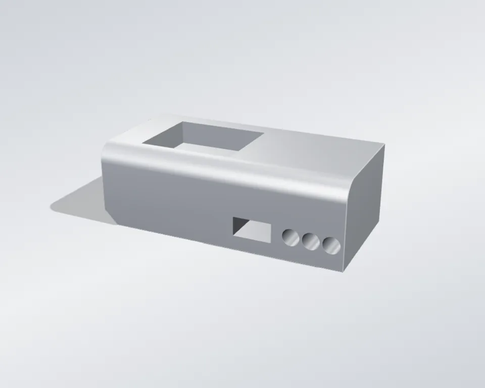
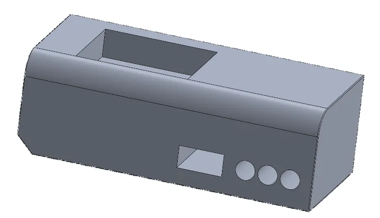
A compact rectangular aluminum block machined to carry a precision sensor-locating pocket, an internal cable pass-through, a three-hole mounting pattern, a lead-in chamfer, and a stress-relief edge fillet. Typical of factory-automation and machine-building applications where a sensor must hold a fixed, repeatable position relative to a moving part or datum surface.
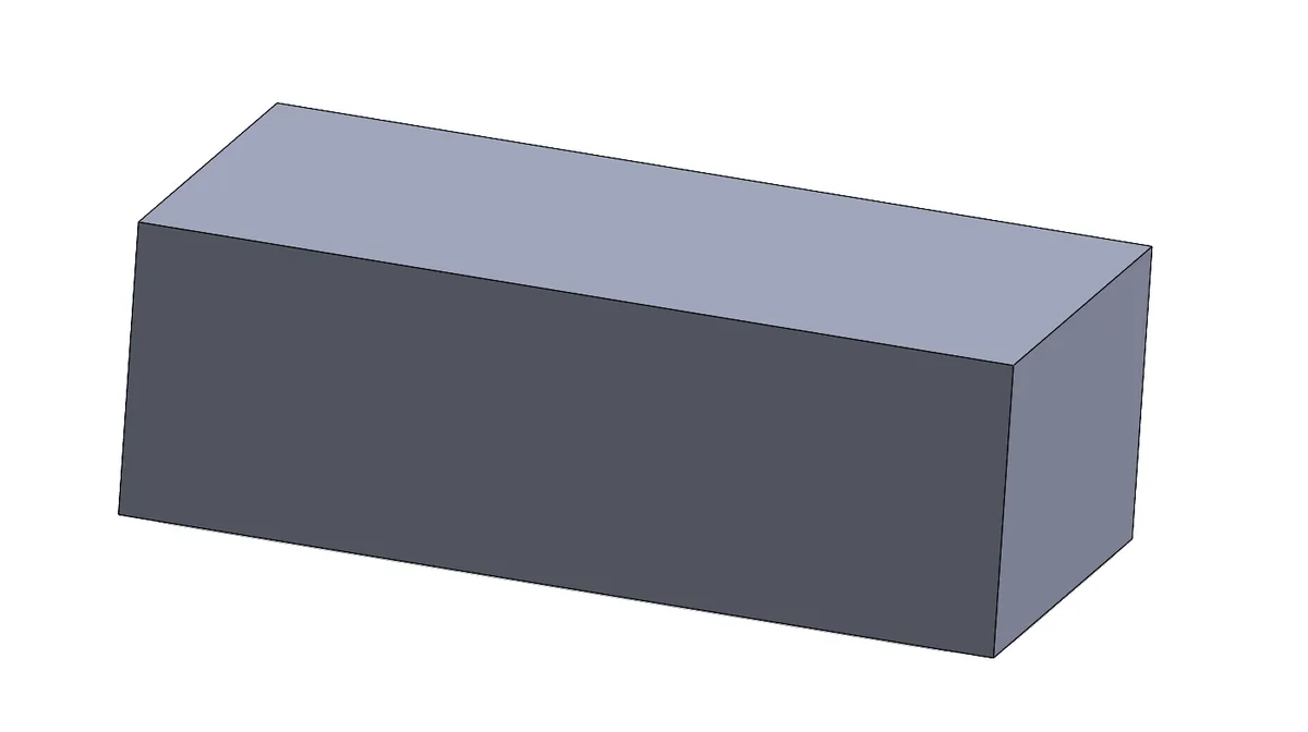
The Primary Design is the raw 105 × 50 × 35 mm aluminum 6061-T6 billet, the un-machined stock envelope.
- Raw stock envelope
- 105 × 50 × 35 mm
- Sensor-locating pocket
- 40 × 34 × 10 mm
- Mounting-hole pattern
- 3 × Ø7 mm
- Finished mass
- 420 g, 6061-T6
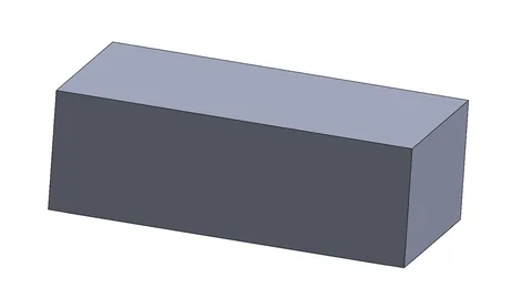
Primary Design (SolidWorks): the raw 105 × 50 × 35 mm aluminum 6061-T6 billet, the un-machined stock envelope. 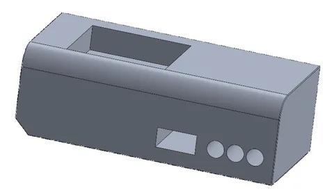
Final Design isometric CAD view (SolidWorks): sensor pocket, cable slot, mounting holes, chamfer, and fillet as-machined. -
Choose the alloy
Material selection
I adopted 6061-T6 aluminum as the reference alloy for its machinability, corrosion resistance, and dimensional stability straight off the shelf, and benchmarked it against two alternative wrought aluminum alloys, 2011-T3 and 7075-T6.
6061-T6 was selected in part for its short, well-broken chips and low cutting forces, reducing cycle time and tool wear relative to a tougher alloy.
- Alloy
- 6061-T6
- Tensile yield strength
- ≈ 255–276 MPa
- Density
- 2.70 g/cm³
- Machinability rating*
- ≈ 50%
Alloys compared Alloy Yield strength Machinability rating* 6061-T6 (adopted) ≈ 255–276 MPa ≈ 50% 2011-T3 ≈ 280–296 MPa ≈ 90% 7075-T6 ≈ 460–503 MPa ≈ 60% -
Plan the setups
SolidWorks
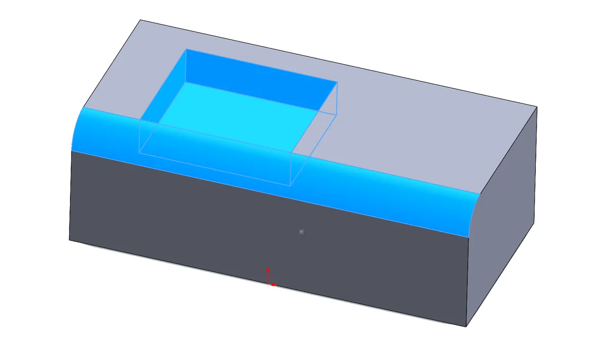
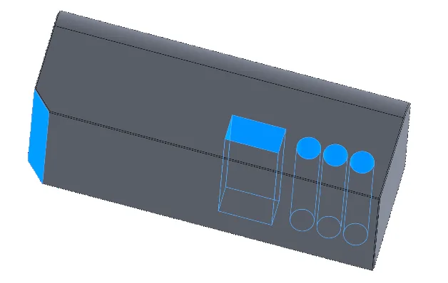
No undercuts, internal cavities, or compound-curved surfaces anywhere on the part, so every feature is cut with a standard cutter from outside the block. Two setups only: Setup 1 (top-face access) cuts the pocket and top-edge fillet; Setup 2 (end-face access, one re-index) cuts the holes, slot, and chamfer, well inside the three-setups-or-fewer guideline.
Every feature is reachable with a standard 3-axis vertical spindle and off-the-shelf cutters: end mills, a twist drill, and a chamfer mill, with no long-reach or angled tooling required.
- Setup 1, top face
- Pocket, top-back R8 fillet
- Setup 2, end face
- Holes, cable slot, chamfer
- Cutters
- End mills, twist drill, chamfer mill
- Setups
- 2 (≤ 3 preferred)
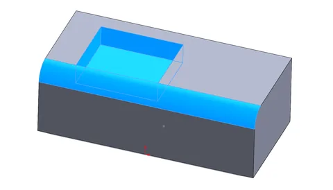
Setup 1 material removal (SolidWorks): the top-back R8 fillet and the 40 × 34 × 10 mm sensor-locating pocket, highlighted. 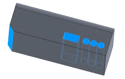
Setup 2 material removal (SolidWorks), viewed from beneath: the lead-in chamfer, cable slot, and mounting-hole pattern, highlighted. -
Draw it and set the pocket tolerances
SolidWorks drawings
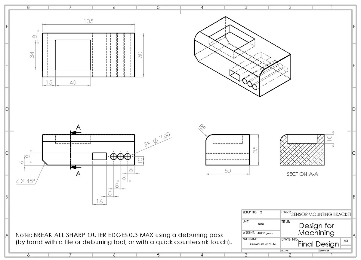
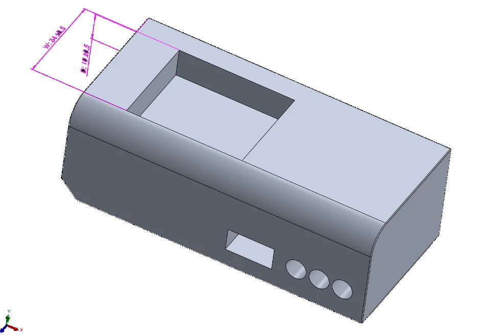
I produced the Final Design manufacturing drawing (Setup 2 / Final Design sheet, full scale). It sets the sensor pocket’s key characteristics, width W = 34 ± 0.5 mm and depth D = 10 ± 0.5 mm, and a 0.3 mm maximum edge break.
Every feature in the raw Primary Design billet was cut in one of two setups on the way to the Final Design.
- Pocket width W
- 34 ± 0.5 mm
- Pocket depth D
- 10 ± 0.5 mm
- Edge break
- 0.3 mm max
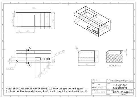
Final Design manufacturing drawing (SolidWorks), Setup 2 / Final Design sheet, full scale. Select to enlarge. 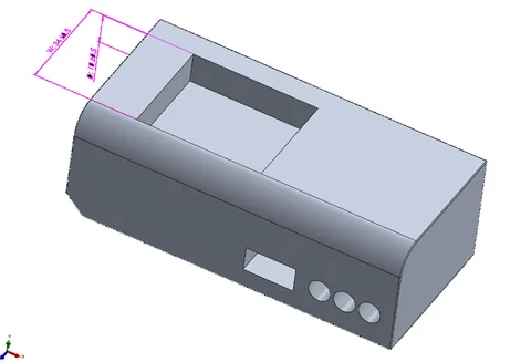
Sensor pocket key characteristics: width W = 34 ± 0.5 mm and depth D = 10 ± 0.5 mm. Select to enlarge.
How I checked the design
The Final Design geometry checks out against published design-for-machining guidelines (Boothroyd, Dewhurst & Knight; Bralla’s Design for Manufacturability Handbook) on seven of the eight rules applied, with the sensor pocket’s internal corner radius flagged as the one open item.
7/8
design rules verified compliant against published machining guidelines
Each rule applied in the method is checked here against a typical guideline range and the value actually achieved in the Final Design, covering setup count, geometry simplicity, pocket proportioning, wall thickness, edge margin, and edge-break callouts.
| Design rule | Value applied | Guideline | Status |
|---|---|---|---|
| Number of setups | 2 | ≤ 3 preferred for prismatic parts | Compliant, favorable |
| Geometry simplicity (no undercuts, cavities, compound curves) | None present | None of these features present | Compliant |
| Pocket depth-to-width ratio, D/W | 10 / 34 ≈ 1 : 3.4 (0.29) | D ≤ 3–4 × W typical | Compliant, conservative |
| Pocket internal corner radius | Not dimensioned on drawing | Must equal/exceed finishing cutter radius, typ. ≥ R2–R3 | Action required |
| Minimum wall / edge thickness | 15 mm minimum | ≳ 3 mm for aluminum, away from load path | Compliant |
| Mounting-hole edge distance | 8 mm center-to-edge, ≈ 4.5 mm wall | ≥ 1–1.5 × hole diameter (≈ 7–10.5 mm) | Compliant |
| Edge-break / deburr callout | 0.3 mm max specified | Explicit min/max value, per ISO 13715 | Compliant |
| Non-functional edge fillet (handling / stress relief) | R8 applied to top-back edge | Optional, recommended on frequently handled edges | Compliant, conservative |
Machining issues mitigated by design
Each rule applied in the method directly manages one or more well-understood machining risks.
- The pocket’s D/W ≈ 0.29 keeps the cutter’s length-to-diameter ratio low, well inside the stable range against tool deflection and chatter, even for a modest-diameter finishing end mill.
- Only one re-index is required, and Setup 2 should locate off the surfaces machined in Setup 1 rather than the as-sawn stock faces, keeping datum stack-up between the two feature groups low.
- The third mounting hole’s 8 mm center-to-edge dimension (≈ 4.5 mm remaining wall) meets the 1× hole-diameter minimum, though it sits below the 1.5× preferred value, so drilling breakout and in-service edge chipping are not expected.
- The cable slot and all three mounting holes are through-features; the 0.3 mm max edge-break requirement removes the resulting burrs before they can nick the sensor cable or cut an assembler’s hand.
- The pocket’s conservative depth-to-width ratio keeps chips from packing against the tool and finished walls, though the CAM program should still specify stepover and coolant/air-blast clearing on the finishing pass.
Engineering judgment and recommendations
Beyond the compliance result, the review surfaces where the design has margin and where follow-on engineering work is still needed.
-
Flagged
Sensor pocket needs an internal corner-radius callout
A rotating end mill cannot cut a true zero-radius internal corner, but the 40 × 34 mm pocket carries no explicit corner-radius dimension on the reviewed drawing. Adding an explicit callout (e.g., R3–R5, tied to the finishing cutter diameter actually selected in CAM) is a same-day drawing correction, not a redesign, and should close out before release.
-
Finalize the sensor part number before release
The 40 × 34 × 10 mm pocket is a round-number placeholder sized for the block-sensor housing family broadly, not one manufacturer’s certified outline drawing. Selecting an actual part number, confirming pocket fit, and adding its mounting-screw holes are still open.
-
CAM toolpath simulation would confirm cycle time
The setup, tool-access, and pocket-proportioning rules applied here are geometric design-guideline checks. Toolpath programming and simulation would confirm cutter selection, stepover, and cycle time for the pocket and slot operations.
-
Confirm alloy against service loads
6061-T6 is the reference alloy here for its machinability and corrosion resistance. 7075-T6 remains a drop-in option if a structural or vibration analysis calls for extra strength margin, and 2011-T3 if volume scales toward bar-stock screw-machine production.
Technical details
Full material and design-change data for engineers who want to go deeper.
Material selection Strength, elongation and machinability of the three wrought aluminum alloys
Material selection
6061-T6 aluminum is adopted as the reference alloy for its machinability, corrosion resistance, and dimensional stability straight off the shelf, benchmarked below against two alternative wrought aluminum alloys.
| Property | 6061-T6 | 2011-T3 | 7075-T6 |
|---|---|---|---|
| Density | 2.70 g/cm³ | 2.83 g/cm³ | 2.81 g/cm³ |
| Ultimate tensile strength | ≈ 290–310 MPa | ≈ 365–380 MPa | ≈ 540–572 MPa |
| Tensile yield strength | ≈ 255–276 MPa | ≈ 280–296 MPa | ≈ 460–503 MPa |
| Elongation at break | ≈ 10–17% | ≈ 12–15% | ≈ 8–11% |
| Machinability rating* | ≈ 50% | ≈ 90% (best of the three) | ≈ 60% |
| Notable characteristic | Best all-round balance of machinability, corrosion resistance, weldability | Free-machining, lower corrosion resistance, limited plate availability | Highest strength, reduced corrosion resistance and weldability |
Method and design evolution The five design principles, and how every feature changed from billet to Final Design
Method
Five design principles, applied in sequence, convert the raw billet into machining-ready geometry: geometry simplification, setup-count minimization, tool access and cutter selection, machinable-material selection, and pocket depth-to-width proportioning.
Pocket rule: D ≤ 3–4 × W | tool L/D ≤ 4–5 : 1 | setups ≤ 3 preferred
- No undercuts, internal cavities, or compound-curved surfaces anywhere on the part, so every feature is cut with a standard cutter from outside the block.
- Two setups only: Setup 1 (top-face access) cuts the pocket and top-edge fillet; Setup 2 (end-face access, one re-index) cuts the holes, slot, and chamfer, well inside the three-setups-or-fewer guideline.
- Every feature is reachable with a standard 3-axis vertical spindle and off-the-shelf cutters: end mills, a twist drill, and a chamfer mill, with no long-reach or angled tooling required.
- 6061-T6 was selected in part for its short, well-broken chips and low cutting forces, reducing cycle time and tool wear relative to a tougher alloy.
- The pocket’s 10 mm depth against its 34 mm width gives D/W ≈ 0.29, roughly ten to fourteen times inside the D ≤ 3–4 × W guideline, so tool deflection and chatter are not a concern.
Design evolution
Every feature in the raw Primary Design billet was cut in one of two setups on the way to the Final Design, summarized feature by feature below.
| Feature | Primary Design | Final Design |
|---|---|---|
| Edges / corners | Sharp, saw-cut throughout | R8 fillet (top-back edge) + 6 × 45° chamfer (left end), all other edges broken 0.3 mm max |
| Top face | Flat, solid | 40 × 34 × 10 mm sensor-locating pocket |
| Interior / end face | Solid block | 16 × 8 mm cable slot; 3 × Ø7 mm mounting holes, 8 mm pitch |
| Setups required | N/A, raw stock | 2 (Setup 1 top-face; Setup 2 end-face after one re-index) |
| Pocket internal corners | N/A | Inherits cutter radius; not yet dimensioned on drawing |
| Manufacturing readiness | Concept / stock envelope only | Machining-ready, one flagged action item remaining |