
200-Bolt Flange Joint for a Large Rocket Nozzle
The 200-bolt flange joining two shells of a large rocket nozzle must stay tight under pressure and heat: it opens by only 0.13 mm, and the bolts work at about half their yield strength. Geometry rebuilt from photographs, loads and bolt preload derived, then nonlinear contact FEA checked by four independent hand calculations.
- Project
- Case study, Cornell University (online course)
- My role
- CAD, drawings, FEA and hand calculations
- Tools
- SolidWorks, Ansys Mechanical
- Method
- Nonlinear contact FEA (bolted joint)
- 0.13mmpeak local flange gap, under pressure and thermal load
- 410–480MPabulk bolt shank stress, below A-286 yield (889 MPa @ 371°C)
- 200bolted connections on the flange
- 4independent hand calculations run alongside the FEA model
Skills shown
How I did it
The middle and lower sections of a large regeneratively-cooled rocket nozzle are joined by a flange carrying 200 bolts. The goal was to check that this joint keeps its bolt stress and its sealing gap within an acceptable margin under bolt preload, internal pressure, and a large thermal excursion, and to build the CAD and FEA models in a way that could be checked at every step.
-
Rebuild the geometry
SolidWorks
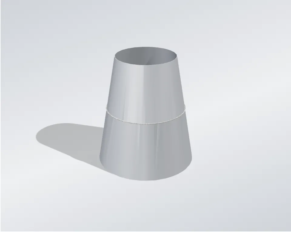
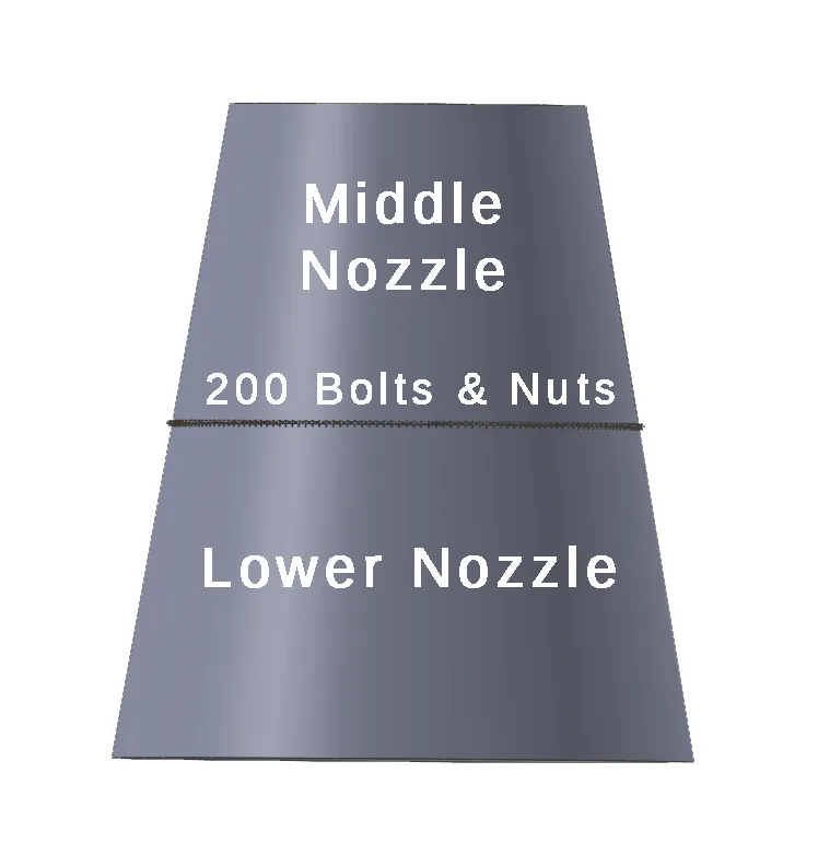
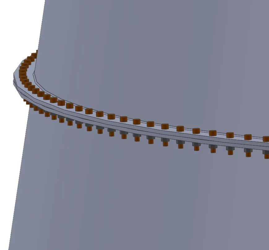
The joint connects the middle and lower nozzle sections through 200 identical bolted connections on a 1.8° angular pitch. No original engineering drawing of this hardware is public, so the geometry was rebuilt in SolidWorks from a photograph-based dimensional survey, calibrated against the one published dimension available (the nozzle exit diameter), then refined during detailed modeling.
- Bolted connections
- 200 on the flange
- Solid bodies
- 4: two shells, bolt, nut
- Total modeled mass
- 3,623 kg
- Angular pitch
- 1.8° between bolts
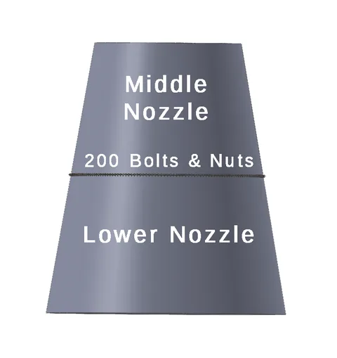
Middle and lower nozzle sections, joined by the 200-bolt flange. 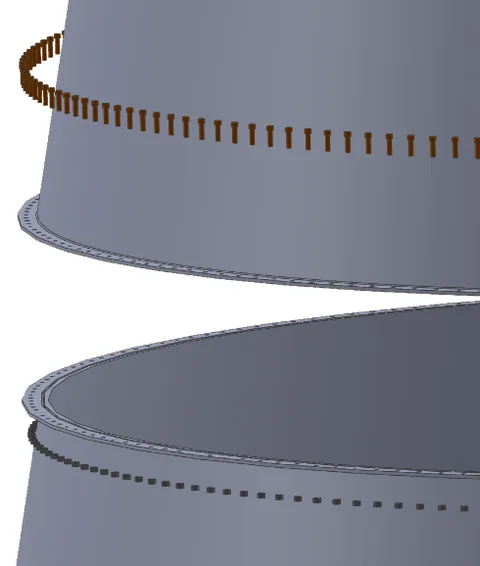
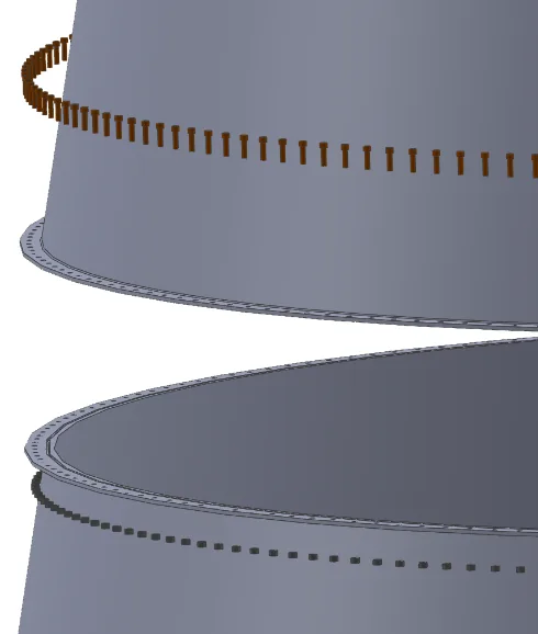
Bolt row along the flange, elevation view. 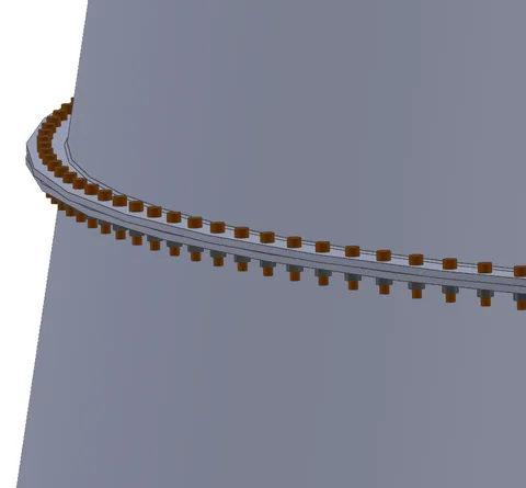
Bolt row detail, used with the exit-diameter calibration to set bolt spacing and count. -
Document it in drawings
SolidWorks drawings
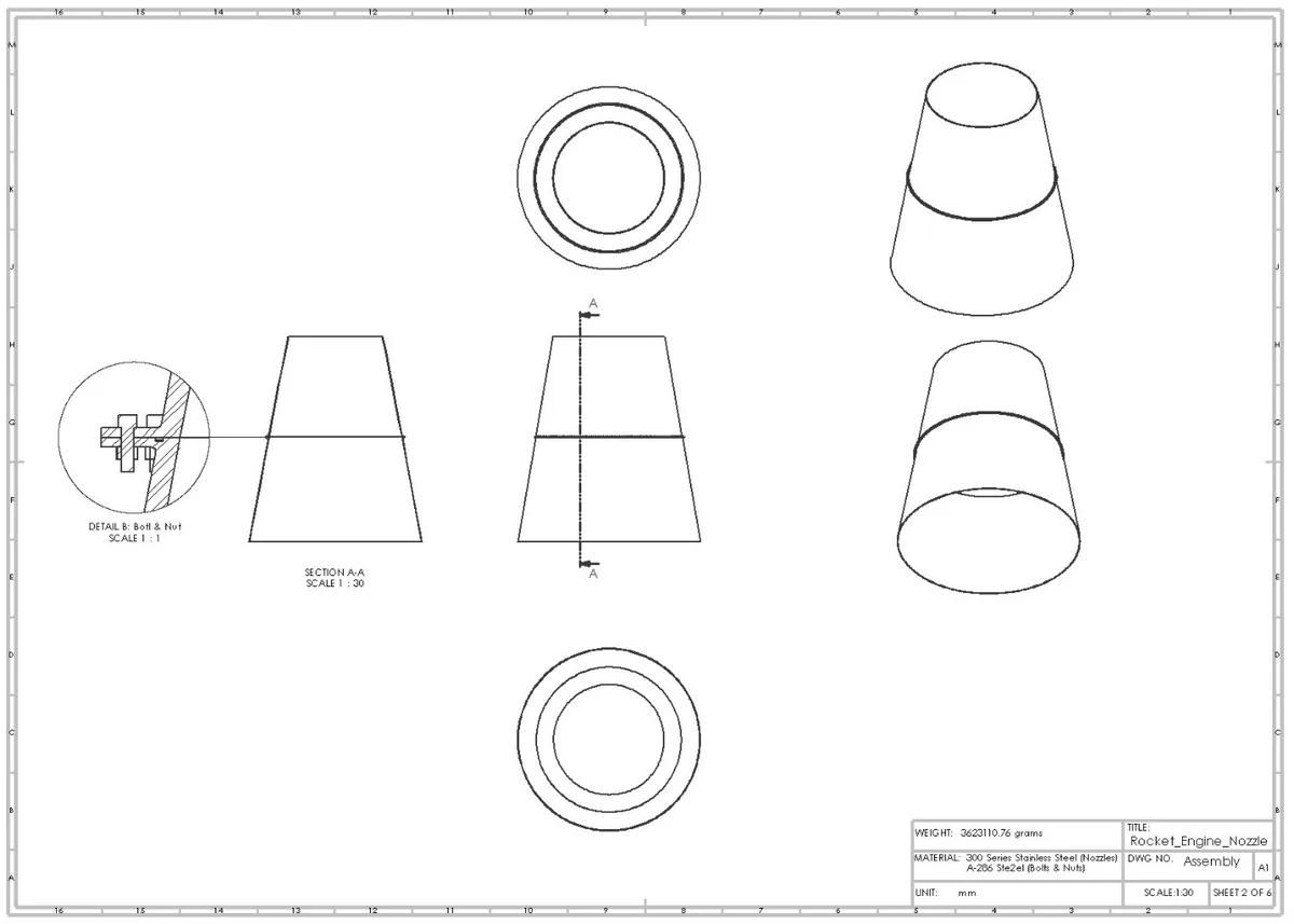
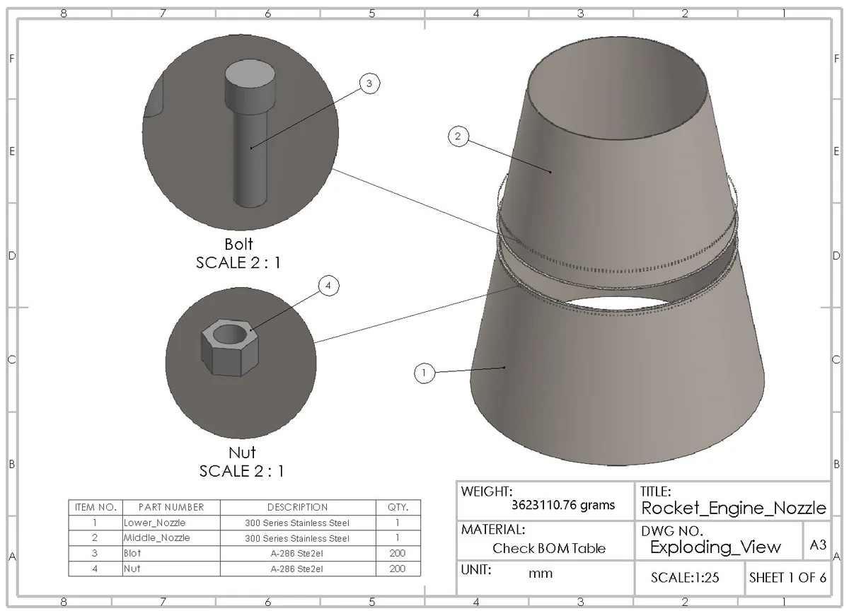
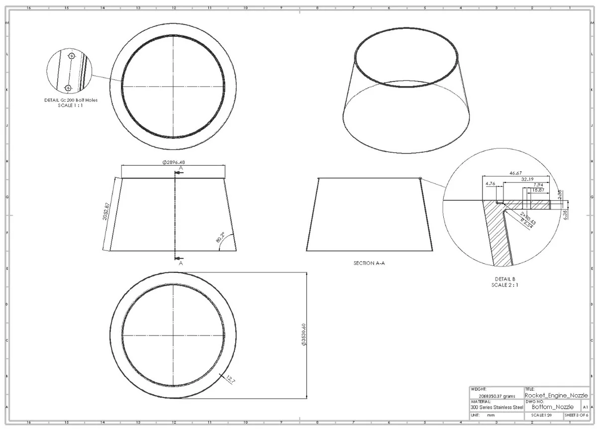
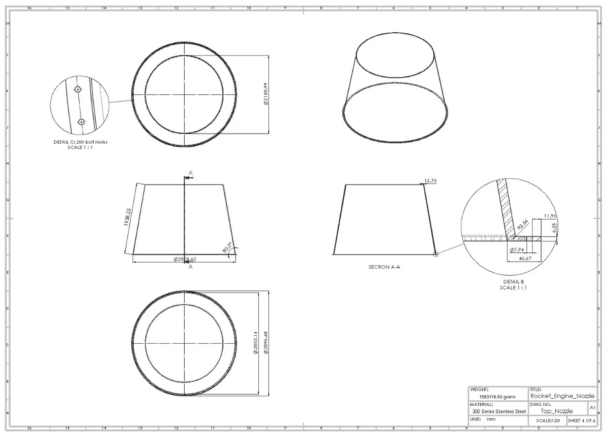
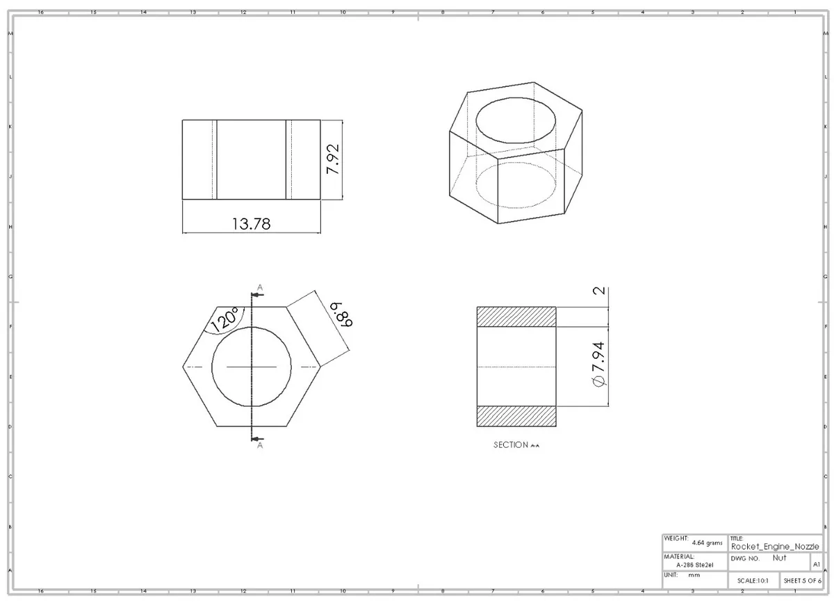
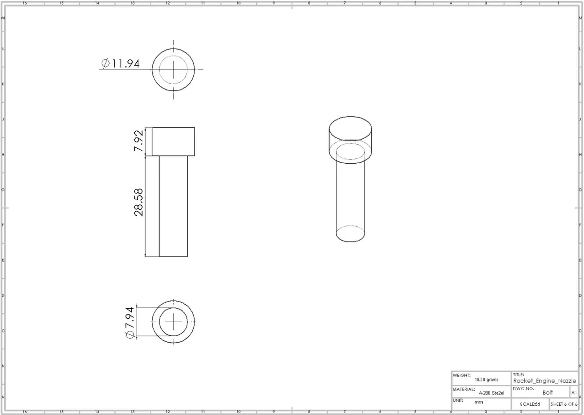
Six drawing sheets document the released geometry: an exploded view with a bill of materials, a full assembly section with a bolt and nut detail, and four individual part drawings, all dimensioned in millimeters. Select a sheet to open it at full resolution.
- Bolt
- A-286, NAS1351 Dash-5, Ø7.94 × 28.58 mm
- Nut
- A-286, 13.78 mm across flats
- Flange
- Ø2,896.48 / Ø2,825.62 mm, 12.70 mm thick
- Nozzle exit
- Ø3,530.60 mm outer
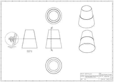
Assembly section and detail, sheet 2 of 6. Select to enlarge. 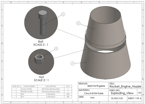
Exploded view and BOM, sheet 1 of 6. Select to enlarge. 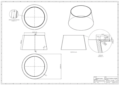
Lower nozzle, sheet 3 of 6. Select to enlarge. 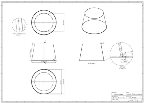
Middle nozzle, sheet 4 of 6. Select to enlarge. 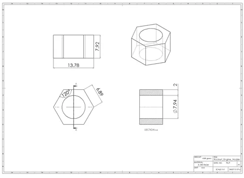
Nut, sheet 5 of 6. Select to enlarge. 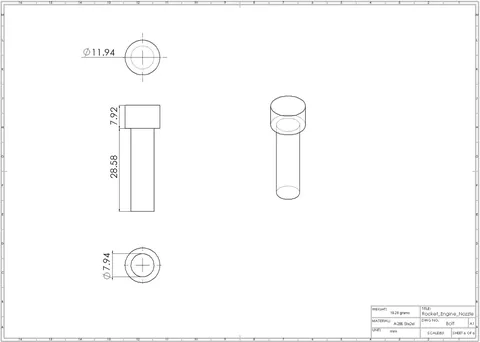
Bolt, sheet 6 of 6. Select to enlarge. -
Select the materials
Material selection
Two materials carry over from the reference design: 300-series austenitic stainless steel for the nozzle shells, and A-286 iron-nickel superalloy for the bolts and nuts. Both are standard choices for regeneratively-cooled nozzle hardware, and the pairing keeps their coefficients of thermal expansion close, which limits how much clamping preload the joint loses as it heats.
- Shells
- 300-series stainless steel
- Bolts and nuts
- A-286 superalloy
- A-286 yield @ 371°C
- 889.4 MPa
- Expansion @ 371°C
- 1.80 / 1.71 ×10⁻⁵/°C
Material properties at 21°C and 371°C Property 300-Series SS @ 21°C 300-Series SS @ 371°C A-286 @ 21°C A-286 @ 371°C Yield strength (MPa) 206.8 126.2 1,034.2 889.4 Ultimate strength (MPa) 517.1 352.7 1,241.1 1,092.1 Elastic modulus (GPa) 199.9 175.5 200.6 172.5 Thermal expansion (×10−5/°C) 1.55 1.80 1.62 1.71 -
Set up the contact model
Ansys Mechanical
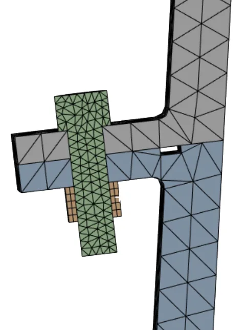
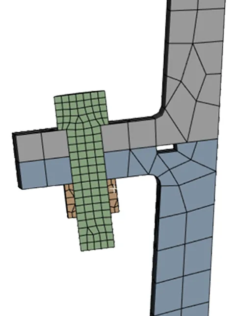
The joint was modeled as a 1/400 angular sector, half of one bolt and nut plus the matching wedge of shell, and solved as a nonlinear static structural problem in three sequential steps: bolt preload, then internal pressure and the regenerative-cooling reaction force, then a uniform temperature rise from 21°C to 371°C. Five frictionless contact pairs capture the bolt threads, the bearing faces, and the flange-to-flange interface where the sealing gap opens.
- Model
- 1/400 sector, half bolt and nut
- Bolt preload
- 20.64 kN (10.32 kN half-bolt)
- Load steps
- Preload → pressure → 371°C
- Mesh
- 25,273 tet → 4,256 hex-dominant elements
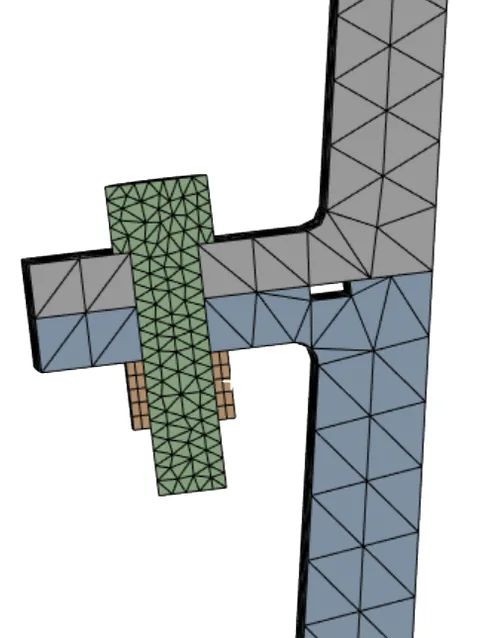
Initial free tetrahedral mesh, 47,648 nodes and 25,273 elements. 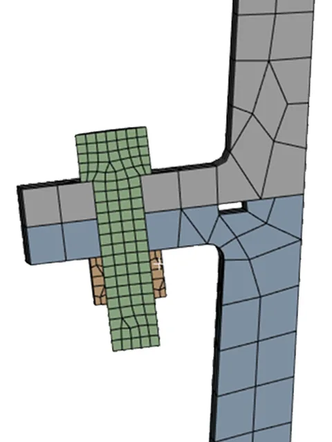
Refined hex-dominant mesh at the same location, 26,135 nodes and 4,256 elements. 
The five frictionless contact pairs defined at the joint: bolt-nut threads, bolt-flange, nut-flange, flange-flange, and bolt-clearance-hole. -
Solve and read the results
Ansys Mechanical
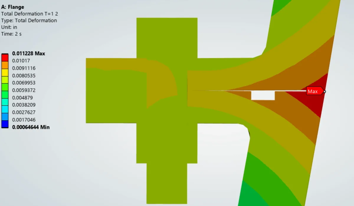
The joint stays fully closed under bolt preload alone. Once pressure and the thermal step are added, a local gap opens at the outer edge of the flange, right at the boundary of typical O-ring sealing allowables (0.13 to 0.25 mm).
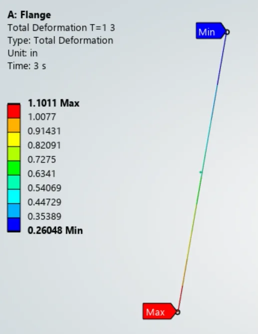
The bulk bolt shank runs 410 to 480 MPa, comfortably below the A-286 yield strength at temperature. The assembly grows about 28 mm axially under the thermal step, and the flange gap barely changes between the pressure and thermal steps, since the shell and the bolt expand at close to the same rate.
- Peak local flange gap
- ≈ 0.13 mm
- Bulk bolt shank stress
- 410–480 MPa
- Axial thermal growth
- 27.9 mm
- Axial reaction
- 3.04 kN
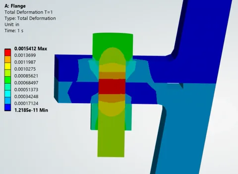
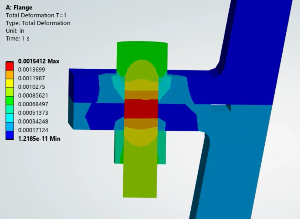
Total deformation under bolt preload, peak 0.039 mm at the bolt / nut. 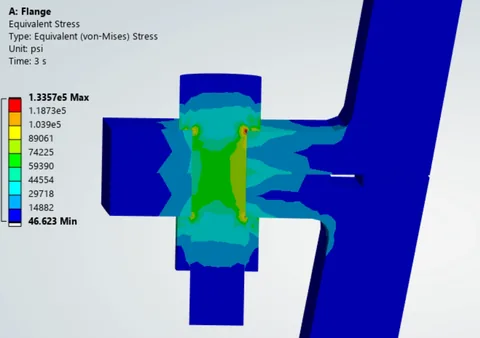
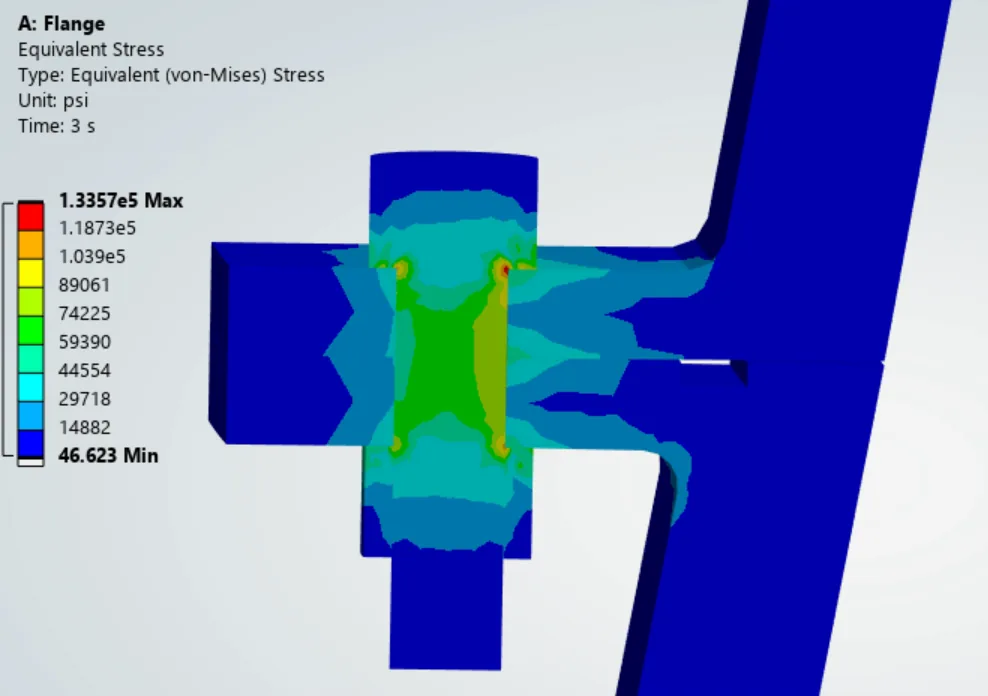
Von Mises stress at the end of the thermal step, bulk bolt shank 410 to 480 MPa. Results and their status Result Value Status Bolt shank equivalent stress (bulk) 410 to 480 MPa Below A-286 yield (889 MPa @ 371°C) Peak local flange gap ≈ 0.13 mm At the edge of typical sealing allowable Cumulative axial thermal growth 27.9 mm Matches free-expansion hand calc within 9% Axial reaction at frictionless support 3.04 kN Within 6% of hand calc

How I checked the results
Four independent hand calculations were run alongside the FEA model: axial reaction force, hoop stress, free thermal growth, and bolt preload stress. Each uses simpler assumptions than the finite element model, so agreement within about 10% is a reasonable bar for confirming the model is behaving physically.
Difference between hand calculation and FEA result
Percent difference for each of the three quantitative checks. Hover a bar for details.
| Quantity | Hand calculation | FEA result | Agreement |
|---|---|---|---|
| Axial reaction force (1/400 sector) | 3.23 kN | 3.04 kN | ≈ 6% |
| Hoop stress at nozzle exit | 11.67 MPa | 11.53 MPa | ≈ 1.2% |
| Axial thermal growth | 25.6 mm | 27.9 mm (cumulative) | ≈ 9% |
| Bolt preload stress | 420.9 MPa | 410 to 480 MPa | Consistent |
Sensitivity and design recommendations
The flange-gap prediction is sensitive to two of the more uncertain inputs. Doubling the regenerative-channel reaction force roughly triples the local gap; halving the bolt preload increases it by about 15%. Bolt preload is something that can be specified directly at assembly, so here is what I would change first if the design needed more sealing margin.
-
Flagged
Increase bolt preload
The lowest-risk, lowest-cost lever: within the margin below the fastener’s rated strength, raising preload reduces the gap and only requires a torque-specification change at assembly, not a geometry change. Its effect is moderate, though (halving preload raised the gap by only about 15%), so for a large gain in sealing margin it is best combined with the flange stiffening below.
-
Add a doubler or thicken the flange locally
Stiffening the flange near the O-ring groove reduces its tendency to deflect open under the separating loads, at the cost of added mass and, for a doubler, an extra part and joint.
-
Increase the flange fillet radius
A larger blend at the flange-to-shell transition reduces local flexibility and the stress concentration there, the same logic used to improve fatigue life at any forged or machined fillet.
-
Refine the regenerative-channel load estimate
This input is both uncertain and the most influential on the gap result. A proper pressure-drop calculation for the cooling circuit would tighten the prediction without changing the physical design.
Engineering judgment and follow-on work
A few follow-on items worth noting, beyond what the results above already cover.
-
Double-check the pressure derivation
The applied pressures came from a hand-derived gas-dynamics calculation rather than a full CFD or vendor-supplied load case. Since the flange-gap result is shown to be sensitive to loads of this kind, it would be worth re-deriving these pressures with more precision before treating the gap prediction as final.
-
Mesh quality flagged for local refinement
A skewness check on the hex-dominant mesh found a small number of elements at the bolt-to-flange corner with elevated skewness. A full three-level mesh-convergence study is recommended before the flange-gap prediction is finalized.
-
Frictionless contact is a conservative simplification
All five contact pairs were modeled frictionless, which is a deliberate, conservative choice but has not yet been checked against a small, nonzero coefficient of friction. That comparison is still open.
-
Fatigue not yet assessed
This analysis covers one steady-state load case. The joint sees repeated start and shutdown cycles in service, so a low-cycle fatigue check of the flange and bolt threads is recommended before the design is finalized.
Technical details
Full geometry data, the simulation set-up, and the three results that carry the design conclusion.
Analysis detail Flange gap at Step 2, axial growth at Step 3, and bolt stress margin
Three results carry the design conclusion: how far the flange gap opens once pressure is applied, how much the assembly grows once it heats up, and how much margin the bolt keeps against the A-286 material strength. Each is isolated below with its own numbers.
A1. Flange gap at Step 2 (pressure + regenerative load)
Primary design check
Once internal pressure and the regenerative-cooling reaction force are added, a small local gap opens between the two flange faces near the outer edge, away from the nearest bolt. This is the interface where the sealing element sits, so it is the result of most direct design significance in the whole study.
The predicted gap sits right at the low end of that allowable range. Not a failure, but limited margin, which is why the sensitivity study and the design recommendations both focus on this number.
A2. Cumulative axial growth at Step 3 (thermal)
Thermal step
With the temperature ramped from 21°C to 371°C and the mechanical loads held constant, the whole assembly grows along its axial length. A deformation probe placed along the modeled section shows how that growth accumulates from the constrained end down to the free end.
The flange gap itself barely moves during this step. Stainless steel and A-286 expand at close to the same rate, so the growth shows up mostly as rigid-body-like axial travel rather than a change in clamping.
A3. Bolt stress margin vs. material capability
Stress check
Away from local stress concentrations, the bulk of the bolt shank carries a fairly uniform equivalent stress. A local peak of about 921 MPa appears at the simplified thread representation used in the bolt/nut contact model. That peak is a modeling artifact of the idealized thread geometry, not a true thread-root stress, so the bulk shank value is the more representative number for a margin check.
The bulk shank stress leaves a healthy margin below yield at temperature, and is consistent with the preload hand calculation covered in the verification section.
Simulation setup Bolt preload, loads, meshing, contact pairs and solver
ΔL = F·L / (E·A)
Bolt pretension adjustment, from applied preload F, shank length L, modulus E, and shank area A.
- Bolt preload set to 50% of the NAS1351 Dash-5 bolt’s minimum breaking strength: 20.64 kN full bolt, 10.32 kN in the half-bolt model.
- Internal pressure derived from 1-D isentropic gas-dynamics theory at the throat, the assembly-top station, and the nozzle exit.
- Regenerative-cooling-channel force applied as an equivalent 4.448 kN concentrated load per flange face, from a free-body diagram of the cooling tubes.
- Hex-dominant meshing at the flange and bolt hole cut the model from 25,273 tetrahedral elements to 4,256 elements at a comparable node count, for faster nonlinear convergence.
- Five frictionless contact pairs: bolt-to-nut threads, bolt-to-flange, nut-to-flange, flange-to-flange (the joint interface), and bolt-to-clearance-hole.
- Full Newton-Raphson solver with automatic sub-stepping, run to convergence at each load step.
Assembly and geometry data Nozzle, flange, bolt and nut dimensions, and the assembly mass
| Component | Parameter | Value |
|---|---|---|
| Lower nozzle | Exit outer diameter | Ø 3,530.60 mm |
| Lower nozzle | Wall thickness | 12.70 mm |
| Flange | Outer / inner diameter | Ø 2,896.48 / Ø 2,825.62 mm |
| Flange | Thickness | 12.70 mm |
| Bolt (A-286, NAS1351 Dash-5) | Shank diameter / length | 7.94 mm / 28.58 mm |
| Nut (A-286) | Width across flats | 13.78 mm |
| Bolt circle | Bolts / nuts, pitch | 200 / 200, 1.8° |
| Full assembly | Total mass | 3,623.11 kg |