
Pillow Block Bearing Housing: Design for Casting
A sharp-edged aluminum bearing housing had to become castable in a reusable metal mold: the redesign needs no core for the bore and meets all ten published casting design rules. I set the parting line, added draft and fillets and removed the core; only the mounting-pad edge is flagged as tight.
- Project
- Personal case study
- My role
- Design review, CAD, drawings and verification
- Tools
- SolidWorks
- Process
- Gravity permanent-mold casting (Al A356.0‑T6)
- 0cores needed for the main bore
- 2°draft on all parting-line-normal faces
- 10/10design rules verified compliant against published casting guidelines
- 156.65gpart mass recorded on the Final Design drawing
Skills shown
How I did it
Take a sharp-edged CAD blank through a systematic design-for-casting review and confirm the resulting geometry is compliant with published DFC guidelines before it goes anywhere near a die builder.
-
Start from the blank
SolidWorks
A two-hole, flange-mounted bearing housing: a raised central tower carrying a through-bore, rising from a solid mounting base plate. Typical of pillow block or plummer block bearing supports used in conveyor systems, agricultural and material-handling equipment, pumps, fans, and general power-transmission machinery.
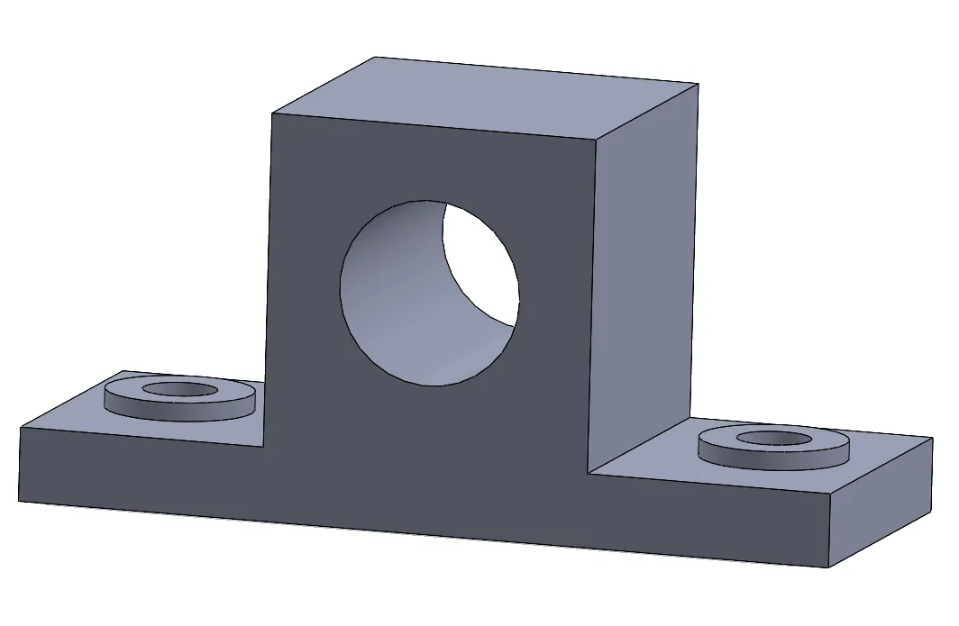
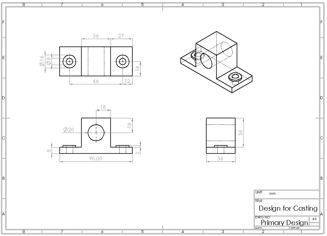
The Primary Design is a sharp-edged, un-drafted CAD blank that fixes the part’s overall envelope, bore, and hole pattern.
- Base-plate envelope (final)
- 88.6 × 34.6 mm
- Through-bore
- Ø20 mm
- Mounting holes
- 2 × Ø8 mm, 66 mm c–c
- Part mass (final)
- 156.65 g
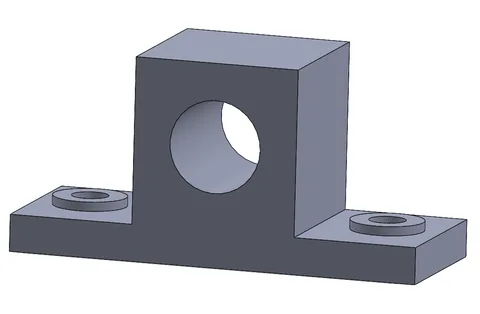
Primary Design surface model (SolidWorks): a sharp-edged, un-drafted CAD blank fixing the part’s overall envelope, bore, and hole pattern. 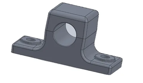
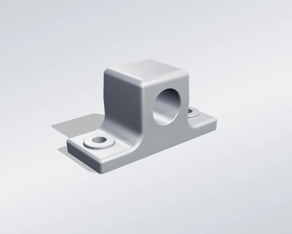
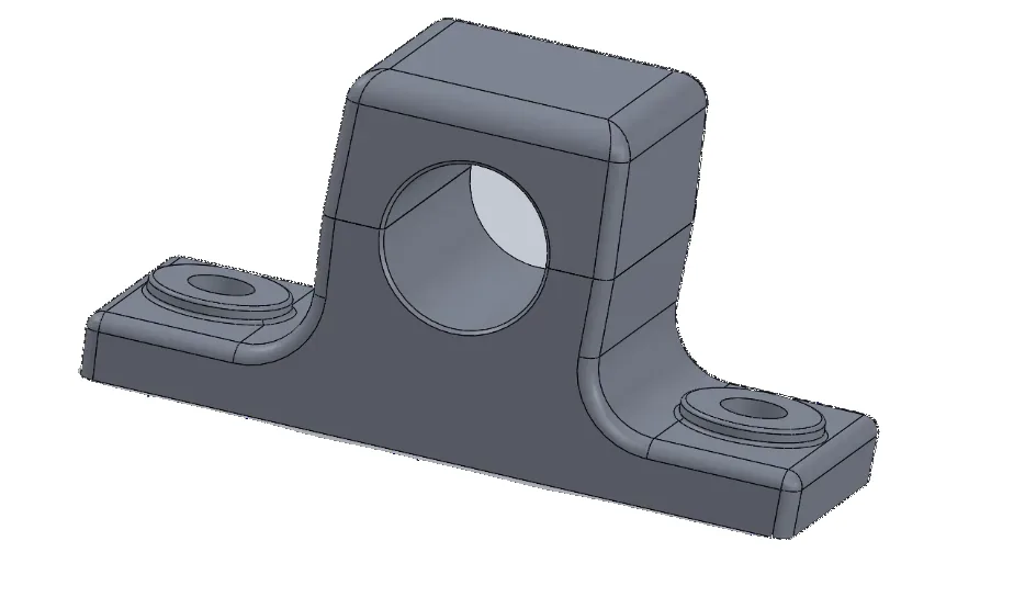
Final Design isometric CAD view (SolidWorks): fully filleted, drafted, casting-ready geometry with a directly die-formed through-bore. -
Choose the material and process
Material and process selection
The design note specifies aluminum only. I adopted A356.0-T6, an Al–Si–Mg gravity permanent-mold casting alloy, as the reference material for its balance of castability, ductility and corrosion resistance, and benchmarked it against A357.0-T6 and A319.0-T6.
Of the three casting routes compared, I adopted gravity permanent-mold casting, consistent with the design note’s own draft-angle and tolerance targets and with the part’s requirement to reach full T6 mechanical properties.
- Alloy
- A356.0-T6
- Process
- Gravity permanent mold
- Typical draft
- 1°–3°
- Typical tolerance
- ±0.13–0.30 mm, CT6–CT8
Casting routes compared, aluminum alloys Process Typical draft Typical tolerance Sand casting 2°–3° ≈ ±0.3–0.5 mm Gravity permanent mold (adopted) 1°–3° ≈ ±0.13–0.30 mm High-pressure die casting 0.5°–2° ≈ ±0.08–0.20 mm -
Apply the casting rules
SolidWorks
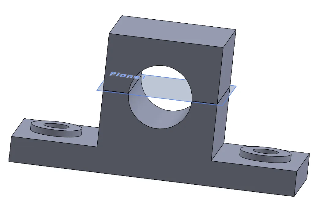
I placed the parting line at the through-bore centerline, the only height at which both die halves retreat from a continuously shrinking, non-overhanging profile, so the bore is formed directly with no core or die slide. I applied a 2° draft to every parting-line-normal face, appropriate to a smooth, coated permanent-mold cavity and tighter than the 3° a sand-cast version of this part would need.
I filleted the base-to-tower junction at R8/R10, at or above the local 8 mm wall thickness, so the part’s principal hot spot does not cool and solidify more slowly than its surroundings. I rounded the tower top corners and base perimeter (R4, R2) to ease die release, and formed the mounting-pad holes with fixed core pins parallel to the draw direction.
- Parting line
- Through-bore centerline
- Draft
- 2°
- Base-to-tower fillets
- R8 / R10
- Cores for the main bore
- 0
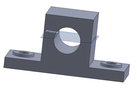
Parting plane (Plane 1) selected at the through-bore centerline, splitting the casting into upper and lower die-cavity halves. -
Compare before and after
SolidWorks drawings
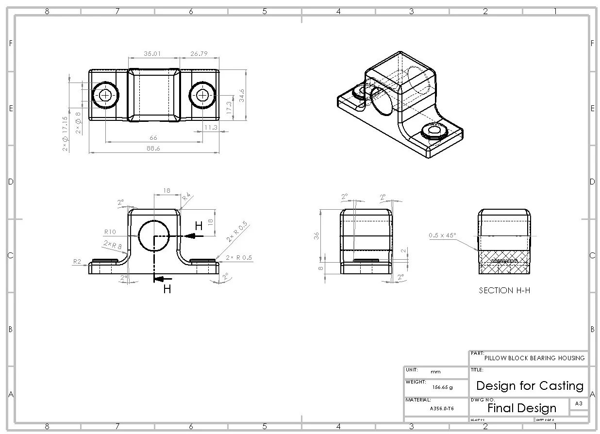
I produced drawings of the Primary Design and the Final Design. Every feature in the sharp-edged blank was reworked for casting on the way to the Final Design.
- Draft
- None → 2°
- Corners and edges
- Sharp → R0.5–R10
- Cores
- 3 assumed → 0 for the bore
- Base plate
- 90 × 36 → 88.6 × 34.6 mm
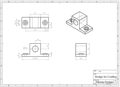
Primary Design drawing, blank envelope, pre-DFC. Select to enlarge. 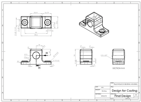
Final Design drawing, casting-ready geometry. Select to enlarge.
How I checked the design
The Final Design geometry checks out fully compliant against published casting design guidelines (ISO 8062-3; EN 1706; Boothroyd, Dewhurst & Knight) on all ten rules applied, with the mounting-pad edge condition flagged as tight and worth a design-review check.
10/10
design rules verified compliant against published casting design guidelines
Each rule applied in the method is checked here against a typical guideline range and the value actually achieved in the Final Design, covering parting-line location, draft angle, fillet and corner radii, core count, and as-cast tolerance.
| Design rule | Value applied | Guideline (Al. gravity permanent mold) | Status |
|---|---|---|---|
| Parting-line location | Coincident with Ø20 bore centerline | Single flat plane at max. periphery / axis of symmetry; no undercuts | Compliant |
| Draft angle | 2° | 1°–3° typical | Compliant |
| Fillet radius at highest-mass junction | R8 / R10 | ≥ local wall thickness, here t ≈ 8 mm | Compliant |
| Corner radius, lower-mass junctions | R4 | ≥ 2–3 mm typical minimum | Compliant |
| Break-edge radius, base perimeter | R2 | 1–3 mm typical | Compliant |
| Mounting-pad edge radius | R0.5 | Sized to preserve a flat seating land | Compliant, tight land |
| Hole breakout treatment | 0.5 × 45° | Chamfer, not fillet | Compliant |
| Core count | 0 required for bore; 2 fixed pins for mounting holes | Minimize / eliminate where geometry allows | Compliant, conservative |
| Re-entrant / undercut features | None present | None permitted without a die slide | Compliant |
| As-cast linear tolerance | ≈ ±0.15–0.20 mm | ≈ ±0.13–0.30 mm typical, CT6–CT8 | Compliant |
Casting defects mitigated by design
Each rule applied in the method directly mitigates one or more well-documented casting defect modes.
- The R8/R10 base-to-tower fillet keeps that junction’s volume-to-surface-area ratio close to the surrounding thin sections, the primary geometric defense against shrinkage porosity at the part’s principal hot spot.
- The same generous fillet radii reduce the local restraint and stress concentration at wall-thickness transitions that drive hot tearing while the casting is still partially liquid and mechanically weak.
- Smooth, generously filleted flow paths and a wall thickness that does not vary abruptly keep the metal front moving hot and continuous, reducing the risk of cold shuts and misruns.
- Melt degassing ahead of pouring addresses gas porosity directly, complementing rather than replacing the geometric hot-spot mitigations above, since dissolved hydrogen is a process- and melt-quality-driven defect rather than a geometric one.
- The 2° draft applied to every parting-line-normal face lets the solidified casting release from the die cleanly, without the galling or tearing that insufficient draft would cause on ejection.
Engineering judgment and recommendations
Beyond the compliance result, the review surfaces where the design has margin and where follow-on engineering work is still needed.
-
Flagged
Mounting-pad land is tight, worth a design-review check
The 2 mm-tall mounting pad, once the 2° draft and even the minimal R0.5 edge fillet are applied, leaves a measurably reduced flat land to seat a bolt head or washer. This should be checked directly against the actual fastener/washer footprint; increasing the pad height to 3–4 mm would give a more comfortable margin at negligible mass cost.
-
Solidification simulation would confirm hot-spot feeding
The fillet sizing and risering strategy applied here are qualitative design-guideline checks. A gating/risering and solidification simulation would numerically confirm the base-to-tower junction feeds and solidifies without trapped shrinkage porosity.
-
Casting trades peak fatigue strength for shape freedom and cost
A permanent-mold aluminum casting reaches a smaller fraction of a forging’s fatigue strength and toughness, an acceptable trade-off for a bearing housing whose governing load is the largely static support of a rotating shaft rather than a high-cycle duty cycle.
-
Confirm alloy temper against service loads
A356.0-T6 is the reference alloy here for its castability, ductility, and corrosion resistance. A357.0-T6 remains a drop-in option if additional strength margin is confirmed necessary, at some cost to elongation and melt-quality tolerance.
Technical details
Full material, process and design-change data for engineers who want to go deeper.
Material and casting process selection Alloy comparison, casting-route comparison and the production route
Material selection
The design note specifies aluminum only; A356.0-T6, an Al–Si–Mg gravity permanent-mold casting alloy, is adopted as the reference material here for its balance of castability, ductility, and corrosion resistance, benchmarked below against two higher-performance alternatives. The Final Design drawing records a part mass of 156.65 g.
| Property | A356.0-T6 | A357.0-T6 | A319.0-T6 |
|---|---|---|---|
| Density | 2.68 g/cm³ | 2.68 g/cm³ | 2.79 g/cm³ |
| Ultimate tensile strength | ≈ 240–300 MPa | ≈ 315–345 MPa | ≈ 230–260 MPa |
| Tensile yield strength | ≈ 170–230 MPa | ≈ 260–290 MPa | ≈ 150–185 MPa |
| Elongation at break | ≈ 3–8% | ≈ 3–6% | ≈ 1.5–2.5% |
| Elastic modulus | ≈ 71 GPa | ≈ 72 GPa | ≈ 74 GPa |
| Notable characteristic | Best balance of strength, ductility, corrosion resistance | Higher Mg and higher strength; a standard alloy for premium aerospace castings | Cu addition improves machinability and cost, reduces elongation and corrosion resistance |
Casting process selection
Three casting routes are compared below; gravity permanent-mold casting is adopted as the process route for this component, consistent with the original design note’s own draft-angle and tolerance targets and with the part’s requirement to reach full T6 mechanical properties.
| Process | Typical draft angle | Typical linear tolerance | Typical ISO 8062-3 grade |
|---|---|---|---|
| Sand casting (Al alloys) | 2°–3° | ≈ ±0.3–0.5 mm | CT9–CT11 |
| Gravity permanent mold (Al alloys) | 1°–3° | ≈ ±0.13–0.30 mm | CT6–CT8 |
| High-pressure die casting (Al alloys) | 0.5°–2° | ≈ ±0.08–0.20 mm | CT4–CT6 |
The selected route pours a degassed, grain-refined A356.0 charge under gravity into a preheated, coated permanent-mold die, actively risers the base-to-tower hot spot until it solidifies, then trims, solution-heat-treats and ages the casting to T6, and finish-machines the bore and mounting holes where the as-cast tolerance does not meet the mating interface.
Method and design evolution The five design operations, and how every feature changed from blank to Final Design
Method
Five design operations, applied in sequence, convert the sharp-edged blank into casting-ready geometry: parting-line selection, draft angle, fillet and corner radii, core planning, and bore-breakout chamfering.
Fillet rule: fillet ≥ local wall thickness | draft = 2° (permanent mold) | parting line at max. periphery / axis of symmetry
- Parting line placed at the through-bore centerline, the only height at which both die halves retreat from a continuously shrinking, non-overhanging profile, forming the bore directly with no core or die slide.
- A 2° draft applied to every parting-line-normal face, appropriate to a smooth, coated permanent-mold cavity and tighter than the 3° a sand-cast version of this part would need.
- Base-to-tower junction filleted at R8/R10, at or above the local 8 mm wall thickness, keeping the part’s principal hot spot from cooling and solidifying more slowly than its surroundings.
- Tower top corners and base perimeter rounded (R4, R2) to ease die release and further reduce hot-spot risk at the lower-mass junctions.
- Mounting-pad holes formed by fixed core pins parallel to the draw direction.
Design evolution
Every feature in the sharp-edged Primary Design blank was reworked for casting on the way to the Final Design, summarized feature by feature below.
| Feature | Primary Design | Final Design |
|---|---|---|
| Drafts | None, vertical un-drafted faces | 2° applied to all parting-line-normal faces |
| Corners / edges | Sharp throughout | Filleted, R0.5–R10 family, plus 0.5×45° bore-breakout chamfer |
| Base-to-tower junction | Sharp 90°, t ≈ 8 mm | R8 / R10 fillets, hot-spot mitigation |
| Mounting pads / spot-faces | Flat Ø16 spot-face, sharp edge, 12 mm edge distance | Ø17.15 spot-face, 2× R0.5 edge fillets, 11.3 mm edge distance |
| Overall base envelope | 90 × 36 mm | 88.6 × 34.6 mm |
| Bore / core strategy | Assumed 3 cores, 2 mounting holes + main bore | 0 cores for main bore, direct die-split; 2 fixed pins for mounting holes |
| Manufacturing readiness | Concept / envelope model only | Casting-ready, compliant with applicable DFC rules |