Frame–Swingarm Pivot Assembly
The eight parts of a motorcycle swingarm pivot must still fit and work with every part at the edge of its tolerance: a worst-case stack-up shows that all five functional requirements hold. The tightest, bolt protrusion beyond the nut, is 0.6 mm against a 0.5 mm minimum; the analysis runs from CAD section views to a signed-off dimensional chain.
- Project
- Personal case study
- My role
- CAD sections, tolerance stack-up and design review
- Tools
- SolidWorks
- Method
- Worst-case (arithmetic) stack-up
- 5/5functional requirements satisfied under worst-case tolerances
- 0.6mmtightest margin: minimum bolt protrusion beyond the nut (target ≥ 0.5)
- 3.4mmwidest margin: maximum bolt protrusion
- 8cataloged components in the axial dimensional chain
Skills shown
How I did it
Verify, under worst-case combinations of component tolerances, that the pivot assembly satisfies five functional requirements, using a conservative 1D arithmetic stack-up so the result holds for 100% of assemblies built within specification, not just a statistical majority.
- The swingarm rotates freely without contacting (fouling) the frame.
- The bolt threads provide sufficient engagement length to be torqued to specification.
- The bolt protrudes beyond the nut enough for full thread engagement, without creating an ergonomic or aesthetic issue.
- The adjuster nut does not contact the nut, preserving its function as an independent adjustment element.
- The adjuster nut does not contact the frame, avoiding stress concentration and wear at the interface.
-
The assembly
SolidWorks · eight cataloged components
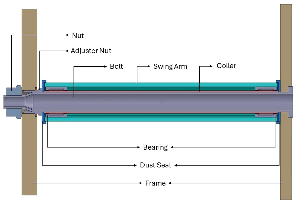
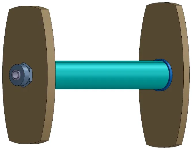
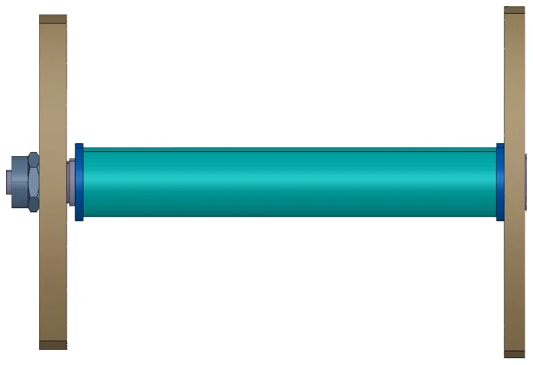
Eight cataloged components arranged concentrically about a common bolt. The bolt clamps the frame walls between the nut and the bolt head, while the swingarm rotates about a collar on a pair of bearings, with a dust seal at each end retaining lubricant and excluding contaminants.
- Cataloged components
- 8
- Functional requirements verified
- 5
- One each
- bolted clamp joint, collar, adjuster nut, swingarm, nut
- Two each
- bearings, dust seals, frames
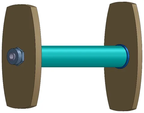
Isometric view of the swingarm assembly. 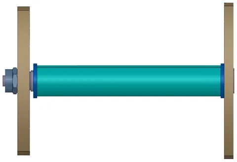
Front view of the swingarm assembly. 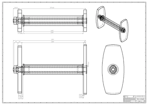
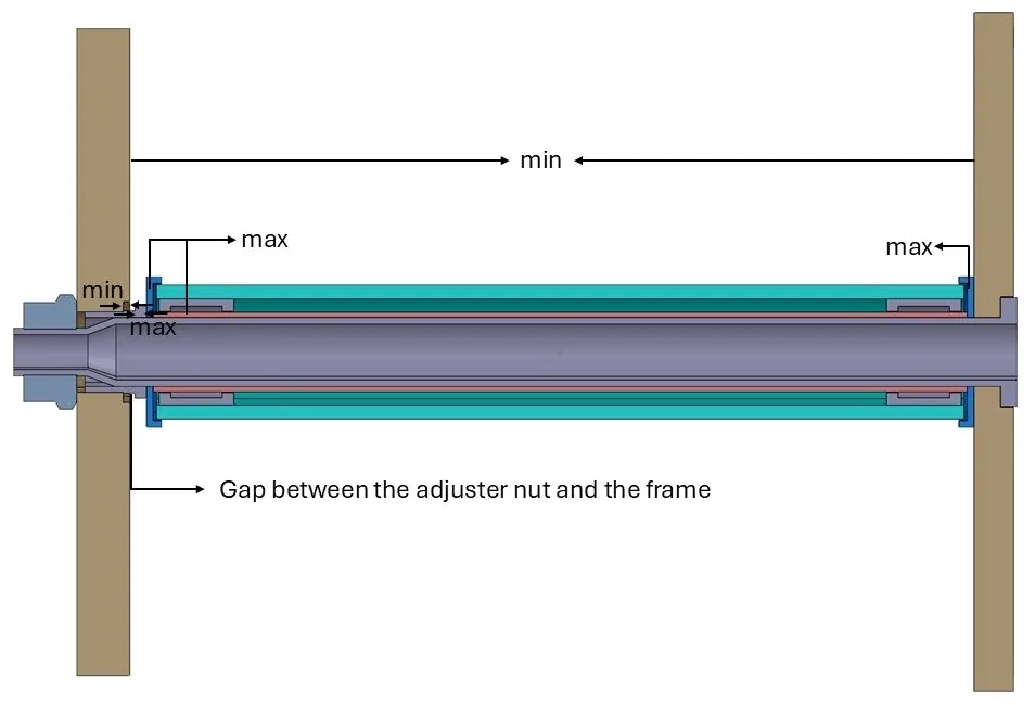
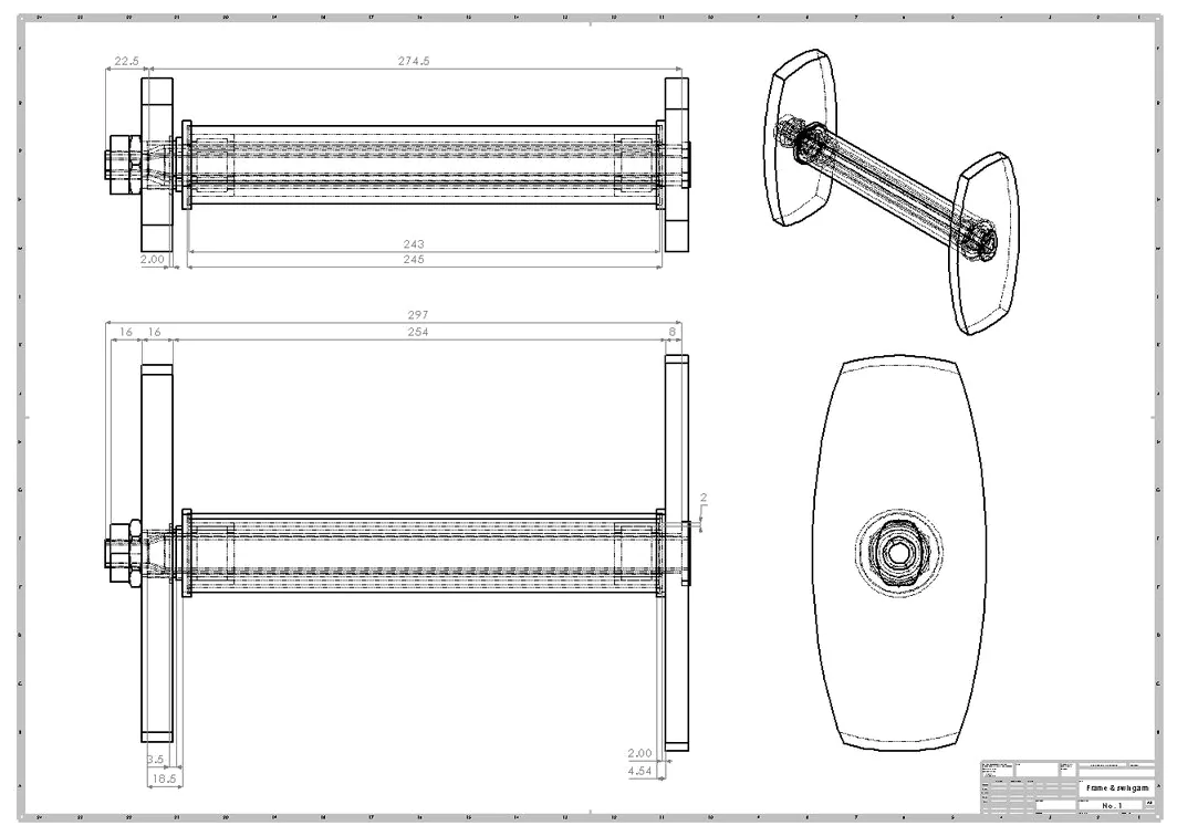
Dimensioned reference drawing, corresponding to the bill of materials and the stack-up equations in the technical details. Select to enlarge. -
Method
Worst-case (arithmetic) 1D stack-up
Each functional requirement is modeled as a linear dimensional chain: component dimensions summed with sign to yield a clearance or engagement length. Substituting the extreme tolerance value at each link bounds the worst physically realizable condition.
Clearance = Σ (dimensions that increase the gap, worst-case) − Σ (dimensions that reduce the gap, worst-case)
- All CAD modeling, parametric sketching, and cross-sectioning for this study were done in SolidWorks.
- Scope is limited to the lateral (axial) dimensional chain along the pivot bore. Radial and torsional load paths are out of scope.
- Worst-case (arithmetic) stack-up: conservative vs. statistical RSS, but guarantees the result for every in-spec assembly.
- Bolt-head geometry is excluded because it doesn’t participate in the lateral chain.
- Pass criterion: a calculated clearance or engagement equal to or greater than the minimum acceptable positive value satisfies the functional requirement. For the maximum protrusion case, the criterion is instead based on the applicable upper limit.
How I checked the results
All five stack-up checks are satisfied under worst-case tolerance conditions. Margins range from a comfortable 3.4 mm down to a comparatively tight 0.6 mm.
5/5
functional requirements satisfied under worst-case tolerances
Every governing equation returns an acceptable clearance or engagement, meaning the requirement holds for 100% of assemblies built from parts within the tolerances listed in the technical details, rather than just the statistical majority a root-sum-square method would guarantee.
Worst-case margin by analysis
Calculated clearance / engagement in mm. Hover a bar for details.
| Functional requirement | Target [mm] | Result [mm] | Status |
|---|---|---|---|
| Swingarm does not foul the frame | ≥ 0.5 | 1.0 | Satisfied |
| Bolt achieves adequate thread engagement | ≥ 1.5 | 2.5 | Satisfied |
| Bolt protrusion beyond the nut is acceptable | ≥ 0.5 | 0.6 (min) | Satisfied, tight margin |
| Adjuster nut does not contact the nut | ≥ 0.5 | 1.4 | Satisfied |
| Adjuster nut does not contact the frame | ≥ 1 | 2.2 | Satisfied |
Each of the five stack-ups, with its dimensional chain, worst-case equation and diagram, is in the technical details.
Engineering judgment and recommendations
Beyond the pass/fail result, the stack-up surfaces where the design has room and where it doesn’t.
-
Flagged
Watch the 0.6 mm bolt-protrusion margin
The tightest result in the report leaves little allowance for effects not modeled here, such as thread run-out, washer/fastener seating, and surface finish. Recommend monitoring in production, or tightening the tolerance on bolt length (E) or nut height (H) if inspection data shows a need.
-
Opportunity: collar tolerance is wider than typical
Collar length (J: ±0.5 mm) is wide relative to what’s typically achievable in a machined part. With 1.0 mm of margin in Analysis 1, there may be room to tighten it, which would be worth a joint review with the supplier on cost and process capability.
-
Bearing & dust-seal dimensions reserved for future work
Bearing wall thickness (M) and dust seal height (N) are recorded in the BOM but not referenced in any of the five lateral-chain analyses here. Retain them for future radial- or preload-stack analyses.
-
Re-run once Cpk data is available
Tolerances used are representative production assumptions, not derived from measured process capability. The analysis should be re-run against real Cpk data once available, to confirm these conclusions hold for actual production variation.
Technical details
The tolerance table and each stack-up in full, for engineers who want to go deeper.
Bill of materials & tolerances Dimensions A–O for the eight parts: nominal, minimum, maximum and tolerance
Representative production tolerances
Sixteen dimensions across eight parts feed the six governing equations in the analysis detail. Values are representative production tolerances, used here to demonstrate the stack-up method.
| Feature | Label | Nominal [mm] | Min [mm] | Max [mm] | Tol. [mm] |
|---|---|---|---|---|---|
| Frame | |||||
| Internal Dimension | A | 254.0 | 254.0 | 255.0 | 1.0 |
| Right Wall Thickness | B | 8.0 | 8.0 | 8.5 | 0.5 |
| Left Wall Thickness | C | 16.0 | 16.0 | 16.5 | 0.5 |
| Recess Depth | D | 2.0 | 1.8 | 2.2 | 0.4 |
| Bolt | |||||
| Bolt Length | E | 297.0 | 296.8 | 297.2 | 0.4 |
| Threaded Length | F | 22.5 | 22.5 | 23.0 | 0.5 |
| Unthreaded (Shank) Length | G | 274.5 | 274.0 | 275.5 | 1.5 |
| Nut | |||||
| Height | H | 16.0 | 15.8 | 16.2 | 0.4 |
| Swingarm | |||||
| Tube Width | I | 243.0 | 243.0 | 243.5 | 0.5 |
| Collar | |||||
| Length | J | 245.0 | 244.5 | 245.5 | 1.0 |
| Adjuster Nut | |||||
| Height | K | 18.5 | 18.3 | 18.7 | 0.4 |
| Recess | L | 3.5 | 3.3 | 3.7 | 0.4 |
| Bearing | |||||
| Wall Thickness | M | 2.0 | 1.8 | 2.2 | 0.4 |
| Dust Seal | |||||
| Height | N | 4.54 | 4.54 | 4.94 | 0.4 |
| Base Height | O | 2.0 | 1.8 | 2.2 | 0.4 |
Analysis detail: the five stack-ups A1–A5: dimensional chain, worst-case equation and result for each requirement
Each analysis isolates one dimensional chain, substitutes the worst-case tolerance extreme at every link, and checks the resulting clearance against the pass criterion.
A1. Swingarm-to-frame rotational clearance
Requirement
The collar length must exceed the swingarm tube width under all tolerance conditions so the swingarm rotates without contacting the frame. Critical case: collar length at minimum, swingarm tube width at maximum.
Clearance = Jmin − Imax
Positive result: the collar remains longer than the swingarm tube width in every combination, preserving 1.0 mm of running clearance.
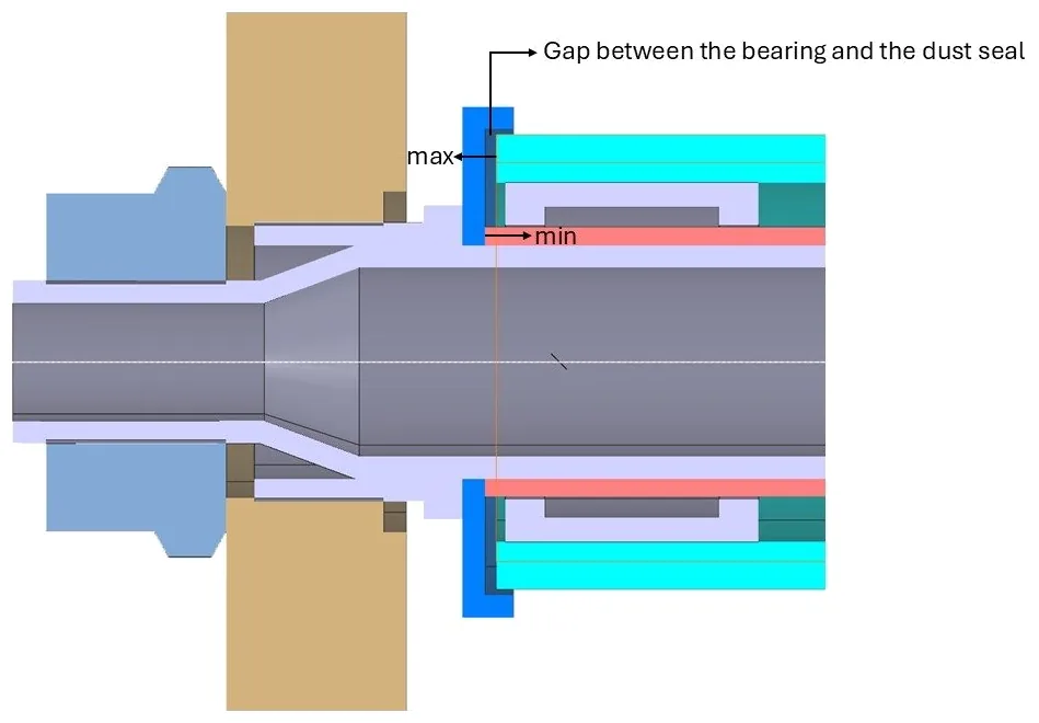
A2. Bolt thread engagement
Requirement
Threaded shank must extend beyond the frame’s outer face so the nut engages full threads rather than the unthreaded step, and can reach specified torque. Critical case: frame envelope at minimum, unthreaded shank at maximum.
Clearance = (Amin + Bmin + Cmin) − Gmax
At least 2.5 mm of threaded shank remains available beyond the wall face under worst-case conditions.
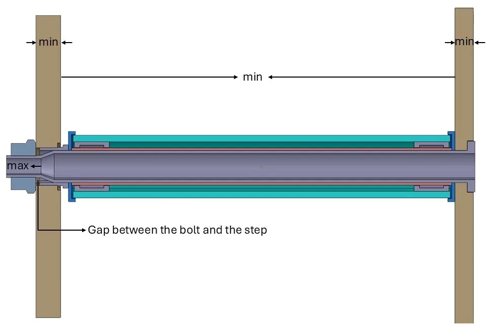
A3. Bolt protrusion beyond the nut
Requirement
The bolt must protrude enough for full thread engagement and clamp load, but not so far as to create an ergonomic or aesthetic issue. Two worst-case conditions are evaluated: longest bolt with thinnest stack (max protrusion), and shortest bolt with thickest stack (min protrusion).
Protrusion = E − (A + B + C + H)
The bolt protrudes 0.6–3.4 mm beyond the nut across the full tolerance range. Full thread engagement holds in every case, but the 0.6 mm minimum leaves little allowance for effects not captured here. See the recommendations.
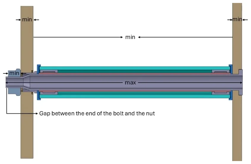
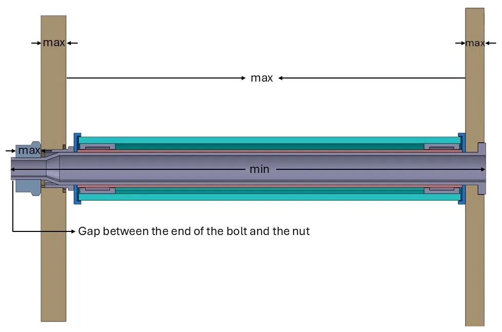
A4. Adjuster nut-to-nut clearance
Requirement
The adjuster nut must not contact the nut, preserving independent adjustment. Critical case: adjuster-side frame envelope at minimum, while collar length, both dust-seal base heights, and adjuster nut height are at maximum.
Clearance = (Amin + Cmin) − (Jmax + Omax,R + Omax,L + Kmax)
1.4 mm of clearance remains between the adjuster nut and the nut under worst-case conditions.
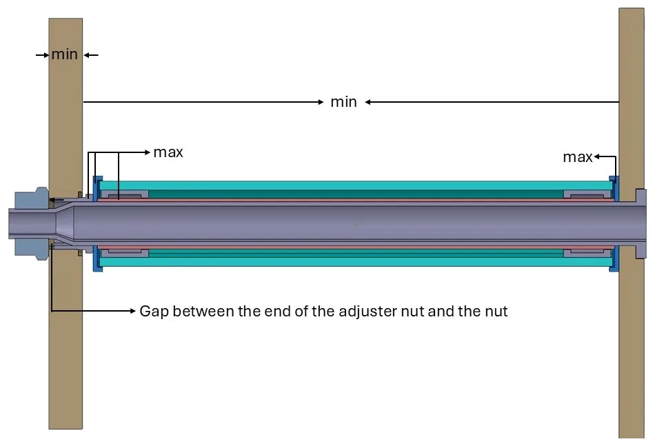
A5. Adjuster nut-to-frame clearance
Requirement
The adjuster nut must not contact the frame at the recess, avoiding stress concentration and wear. Critical case: frame internal dimension and recess depth at minimum, while collar length, dust-seal base heights, and adjuster nut recess are at maximum.
Clearance = (Amin + Dmin) − (Jmax + Omax,R + Omax,L + Lmax)
2.2 mm of clearance remains between the adjuster nut and the frame under worst-case conditions.